
Systems and methods for forming a time-averaged line image

a time-averaged line image and system technology, applied in the field of line images, can solve the problems of inability to use a binary optic approach to produce a line image with the required degree of intensity uniformity, and the coherence length of a cosub>2 /sub>laser is relatively long,

Inactive Publication Date: 2011-09-27
ULTRATECH INT INC
View PDF2 Cites 31 Cited by
  • Summary
  • Abstract
  • Description
  • Claims
  • Application Information

AI Technical Summary

Benefits of technology

[0007]An aspect of the disclosure is a line-image-forming optical system that includes a primary laser system configured to provide a first laser beam. The optical system also includes a beam-conditioning optical system having an image plane and configured to receive the first laser beam and form therefrom a line image at the image plane. The line image has a long axis and a first amount of intensity non-uniformity along the long axis. The optical system also includes one of: a) a secondary laser system that forms a second laser beam, and b) a

Problems solved by technology

However, the coherence length for a CO2 laser is relatively long, typically several meters.
This makes it unfeasible to use a binary optic approach to produce a line image with the required degree of intensity uniformity, i.e., ˜10% (i.e., about + / −5%) based on principles of Kohler illumination.

Method used


Image

  • Systems and methods for forming a time-averaged line image
  • Systems and methods for forming a time-averaged line image
  • Systems and methods for forming a time-averaged line image

Examples


Embodiment Construction

[0030]Reference is now made in detail to embodiments of the disclosure, examples of which are illustrated in the accompanying drawings. Whenever possible, the same or like reference numbers and symbols are used throughout the drawings to refer to the same or like parts.

[0031]It is noted that the term “line image” is used herein in to generally denote an elongate intensity distribution of light formed by a light beam at an image plane, and thus does not necessarily require an associated “object” in the classical sense. For example, the line image can be formed using beam-conditioning optics that cause the aforementioned light beam to come to a line focus at the image plane.

[0032]Also, a “time-averaged line image” is defined herein as a line image whose intensity is measured over a period of time and is averaged over that period of time.

Line-Image-Forming Optical System

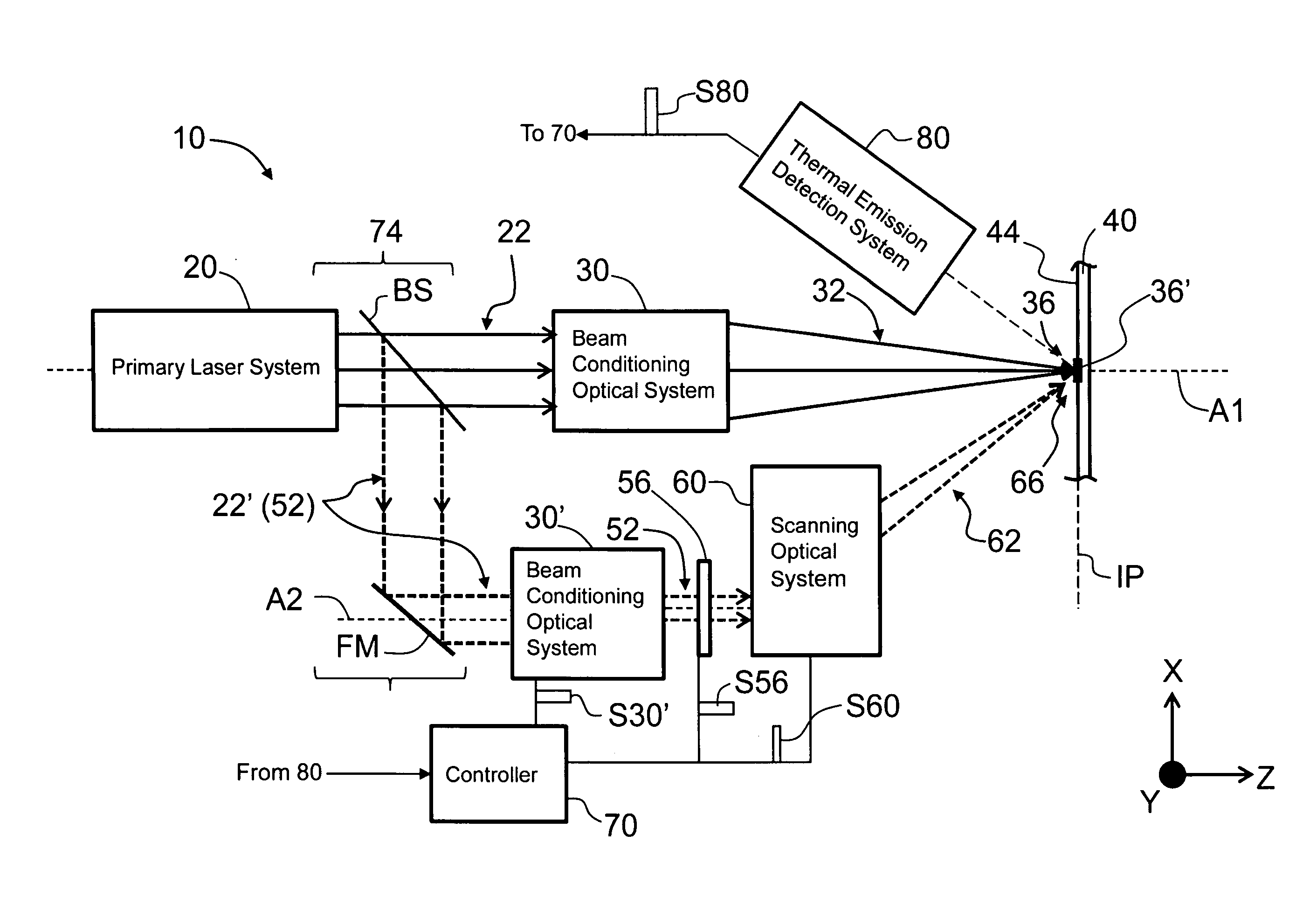
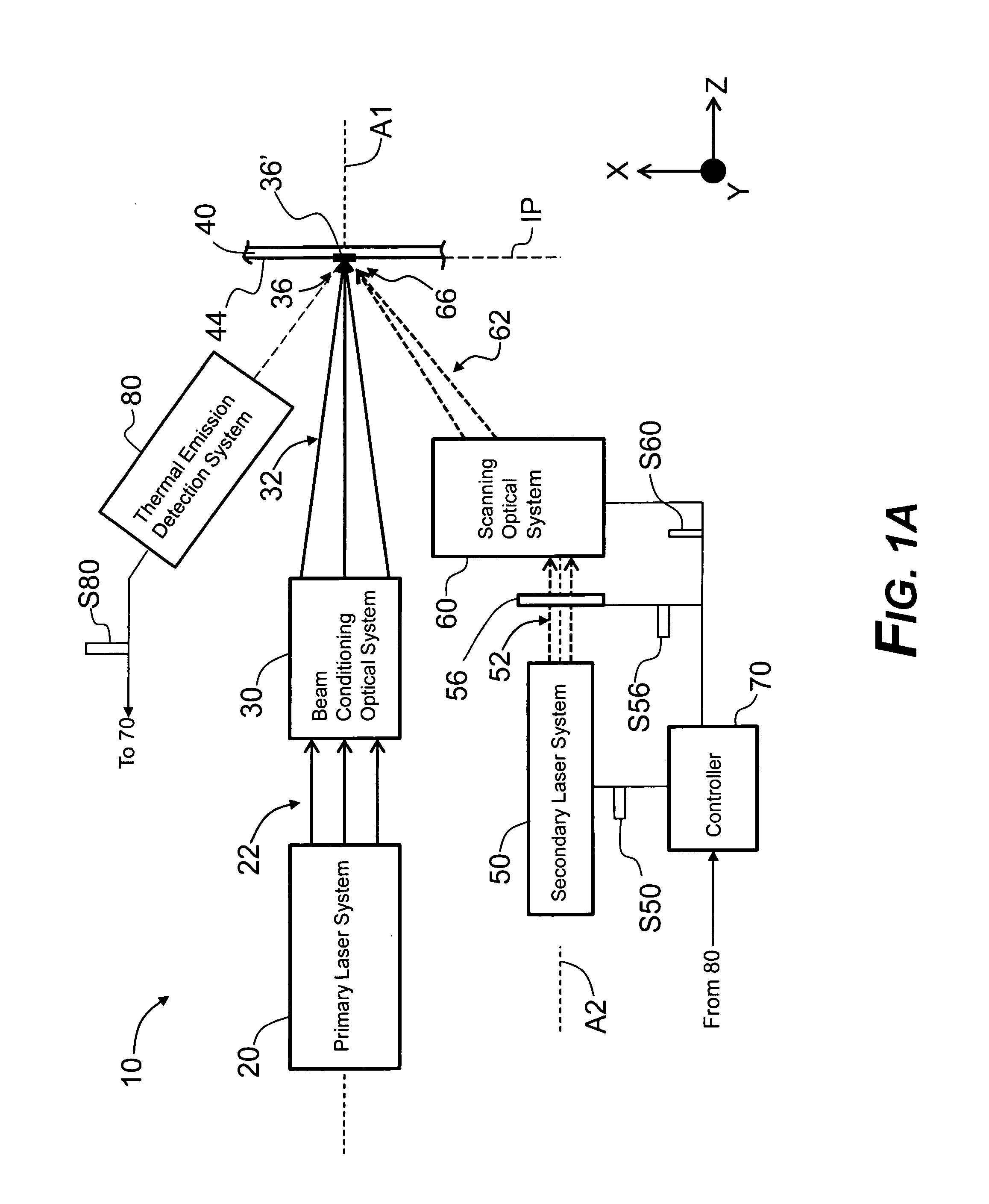
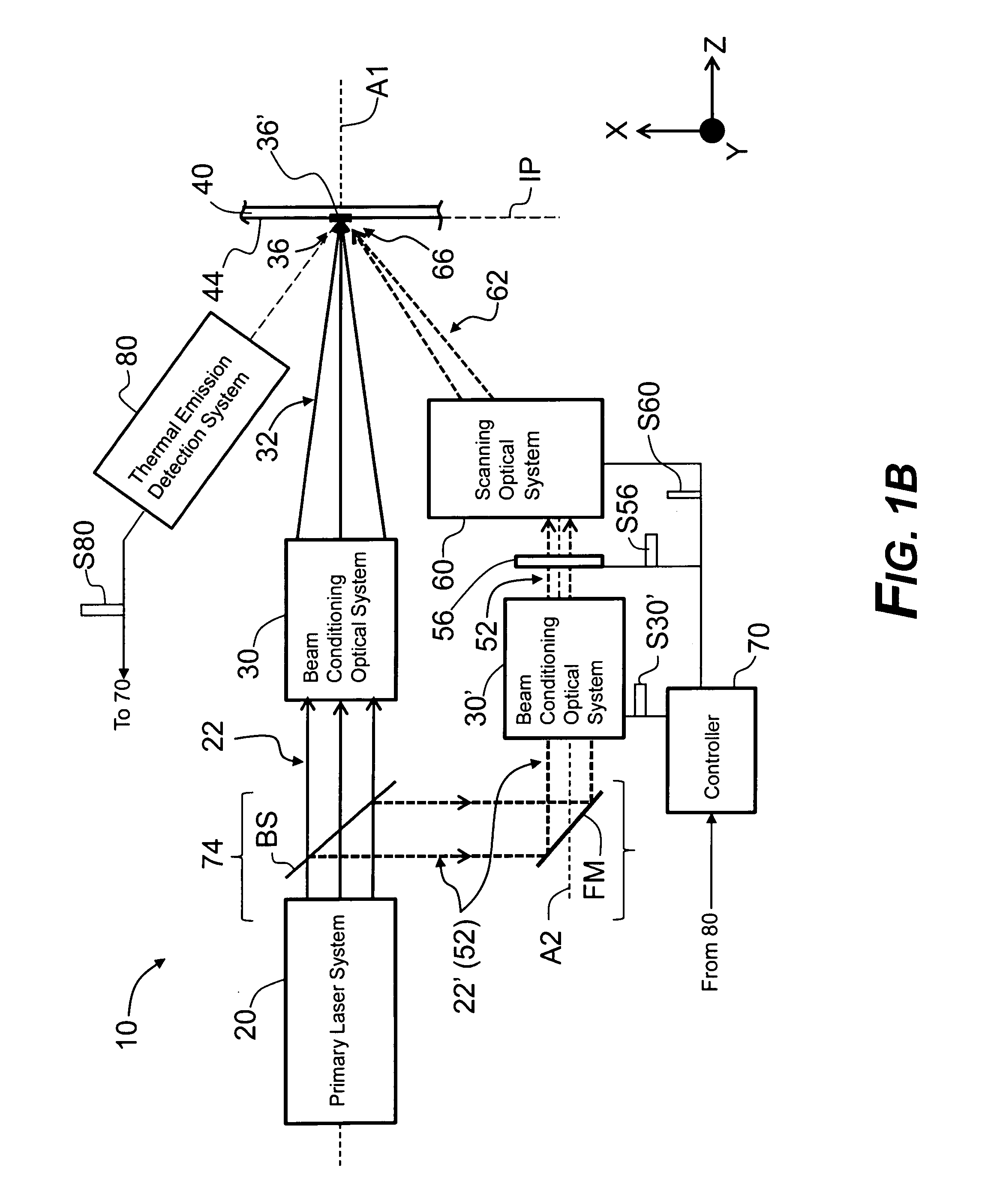
[0033]FIG. 1A is a general schematic diagram of an example line-image-forming optical system (“system”) 10 according ...


PUM

PropertyMeasurementUnit
Timeaaaaaaaaaa
Wavelengthaaaaaaaaaa

Abstract

Systems and methods for forming a time-averaged line image having a relatively high amount of intensity uniformity along its length is disclosed. The method includes forming at an image plane a line image having a first amount of intensity non-uniformity in a long-axis direction and forming a secondary image that at least partially overlaps the primary image. The method also includes scanning the secondary image over at least a portion of the primary image and in the long-axis direction according to a scan profile to form a time-average modified line image having a second amount of intensity non-uniformity in the long-axis direction that is less than the first amount. For laser annealing a semiconductor wafer, the amount of line-image overlap for adjacent scans of a wafer scan path is substantially reduced, thereby increasing wafer throughput.

Description

FIELD[0001]The present disclosure relates generally to the use of line images, and in particular relates to systems and methods for forming a time-averaged line image having a relatively high degree of intensity uniformity.BACKGROUND ART[0002]There are a variety of applications that require the use of a line image having a relatively uniform intensity. One such application is laser thermal processing (LTP), also referred to in the art as laser spike annealing (LSA), or just “laser annealing.” Laser annealing is used in semiconductor manufacturing for a variety of applications, including for activating dopants in select regions of devices (structures) formed in a semiconductor wafer when forming active microcircuits such as transistors.[0003]One form of laser annealing uses a scanned line image from a light beam to heat the surface of the wafer to a temperature (the “annealing temperature”) for a time long enough to activate the dopants in the semiconductor structures (e.g., source a...

Claims


Application Information

Patent Timeline
IPC IPC(8): H01L29/04
CPCB23K26/0066B23K26/006H01L21/268B23K26/0738B23K26/352B23K26/55B23K26/067H01L21/324
Inventor ANIKITCHEV, SERGUEIMCWHIRTER, JAMES T.GORTYCH, JOSEPH E.
Owner ULTRATECH INT INC
Features
  • Generate Ideas
  • Intellectual Property
  • Life Sciences
  • Materials
  • Tech Scout
  • Unparalleled Data Quality
  • Higher Quality Content
  • 60% Fewer Hallucinations
Learn More