
Liquid crystal display comprising a biaxial plate and a C-plate

a liquid crystal display and biaxial plate technology, applied in non-linear optics, instruments, optics, etc., can solve the problem that the existing processing technique cannot increase the retardation in the thickness direction of the compensation plate, and achieve the effect of high accuracy, easy implementation, and high efficiency of viewing angle compensation

Active Publication Date: 2011-09-27
STANLEY ELECTRIC CO LTD
View PDF10 Cites 0 Cited by
  • Summary
  • Abstract
  • Description
  • Claims
  • Application Information

AI Technical Summary

Benefits of technology

The patent text describes a problem in viewing angle compensation in liquid crystal displays having a high retardation value (about 600 nm or more) in the liquid crystal layer. Existing processing techniques cannot provide sufficient retardations in the thickness direction of the plate, so a need exists for a new technique to improve viewing angle compensation. The patent proposes a solution by providing a viewing angle compensation plate that can achieve optimum viewing angle compensation and solve the viewing angle problem associated with the wider viewing angle.

Problems solved by technology

However, the existing processing technique cannot increase the retardation in the thickness direction of the compensation plate.

Method used


Image

  • Liquid crystal display comprising a biaxial plate and a C-plate
  • Liquid crystal display comprising a biaxial plate and a C-plate
  • Liquid crystal display comprising a biaxial plate and a C-plate

Examples


Embodiment Construction

[0044]A description will now be given of exemplary embodiments that are constructed in accordance with principles of the presently disclosed subject matter with reference to the accompanying drawings.

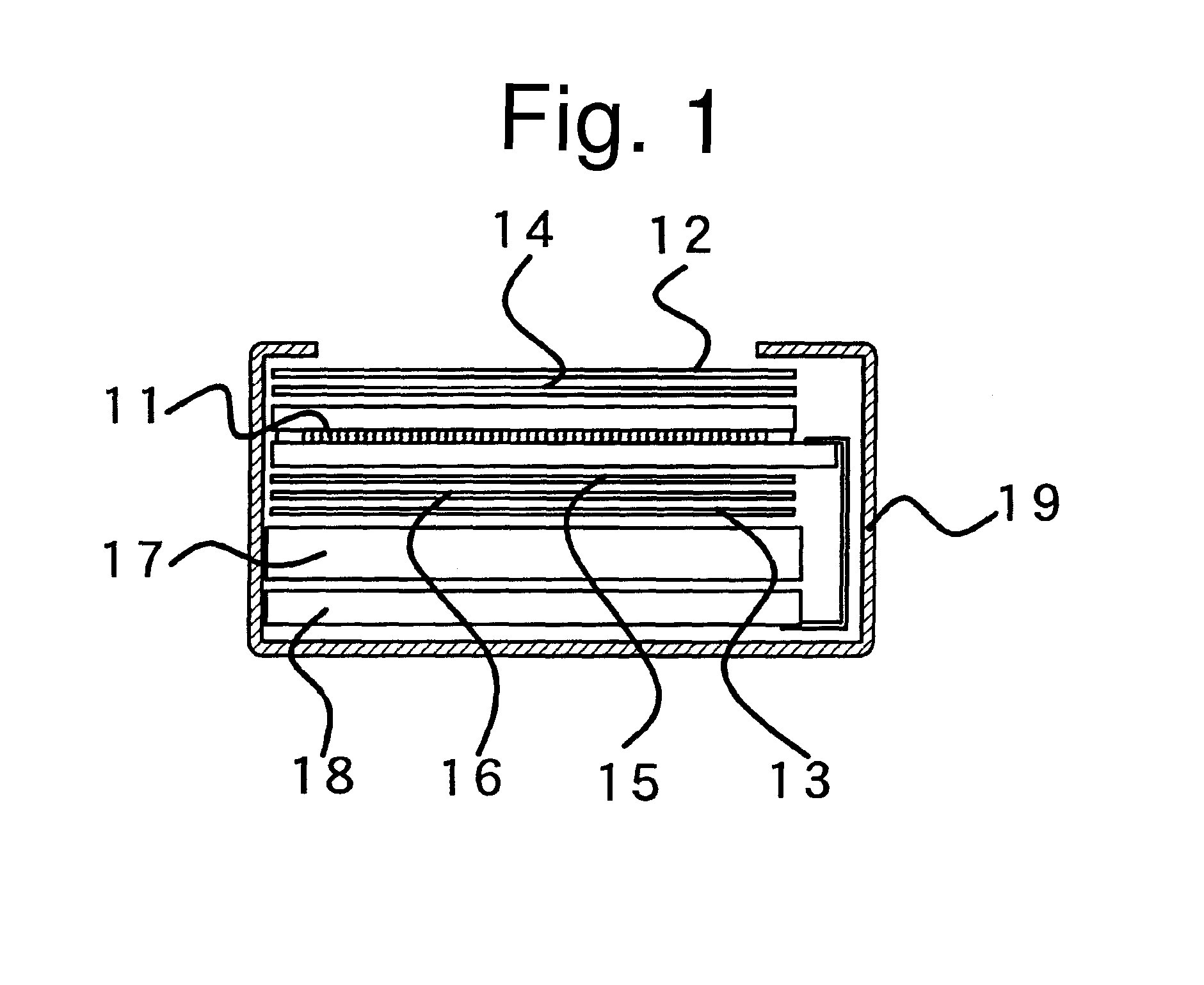
[0045]FIG. 1 shows a schematic configuration of a liquid crystal display of a first exemplary embodiment.

[0046]This liquid crystal display can be driven based on a simple-matrix driving method using a duty ratio of 1 / 4 or more.

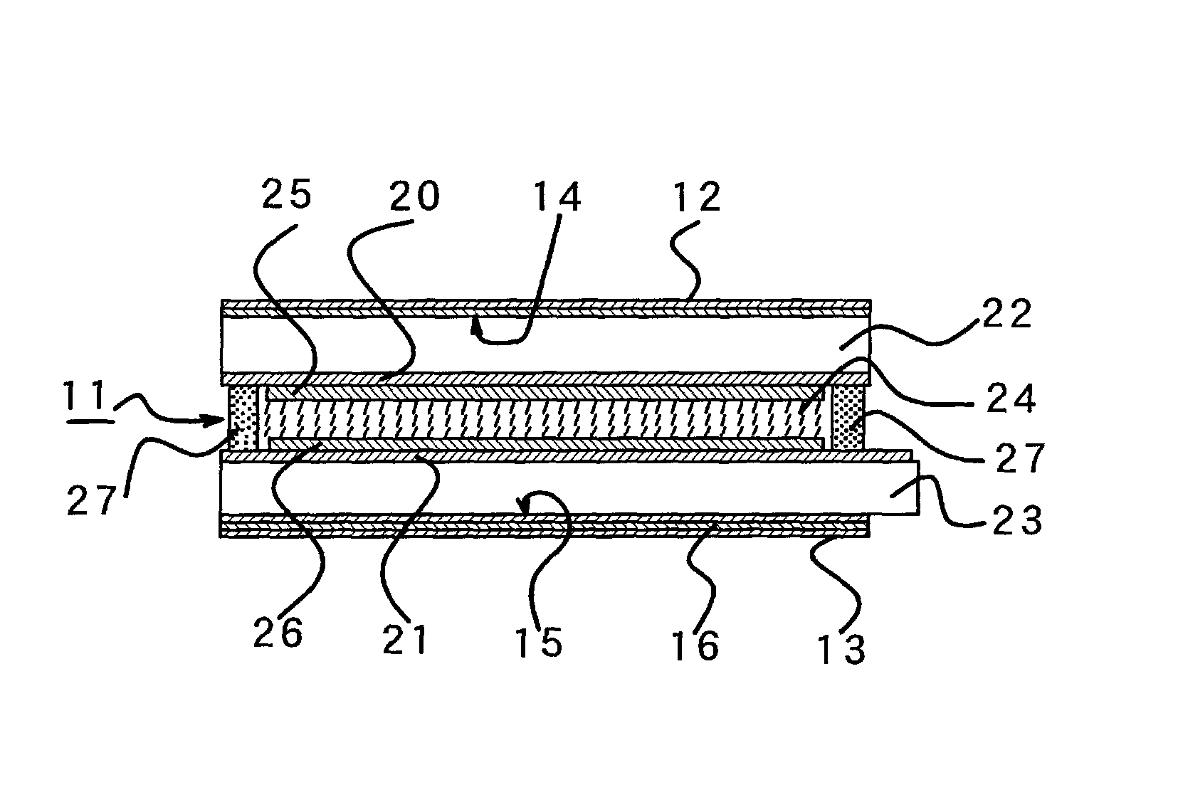
[0047]The liquid crystal display according to this embodiment includes a liquid crystal cell 11, polarizing plates 12 and 13 disposed on respective sides of the liquid crystal cell 11, a biaxial plate 14 disposed between the liquid crystal cell 11 and the polarizing plate 12, and two C-plates 15 and 16 disposed between the liquid crystal cell 11 and the polarizing plate 13.

[0048]In addition to this, the liquid crystal display can include a backlight unit 17, a drive circuit board 18, and the like. The components can be enclosed by a resin cover 19, for example, to...


PUM

PropertyMeasurementUnit
thicknessaaaaaaaaaa
viewing anglesaaaaaaaaaa
diameteraaaaaaaaaa

Abstract

A vertical alignment type liquid crystal display, which has a liquid crystal layer whose retardation value is about 600 nm or more, can solve the viewing angle problems associated with the wider viewing angle. The liquid crystal display can include a vertical alignment liquid crystal cell, and first and second polarizing plates cross-Nicol disposed on respective sides of the liquid crystal cell. The liquid crystal cell has a liquid crystal layer with a retardation of about 600 nm or more. A biaxial plate is provided between the liquid crystal cell and the first polarizing plate, and two C-plates are provided between the liquid crystal cell and the second polarizing plate.

Description

[0001]This application claims the priority benefit under 35 U.S.C. §119 of Japanese Patent Application No. 2006-129869 filed on May 9, 2006, which is hereby incorporated in its entirety by reference.BACKGROUND[0002]1. Technical Field[0003]The disclosed subject matter relates to a liquid crystal display of a vertical alignment type. In particular, the presently disclosed subject matter relates to a liquid crystal display having a liquid crystal layer with a retardation of about 600 nm or more and an effective viewing angle compensation structure therefor.[0004]2. Description of the Related Art[0005]In recent years, viewing angle compensation means having a variety of optical characteristics have been proposed for vertical alignment type liquid crystal displays. In particular, examples of such viewing angle compensation means include viewing angle compensation plates.[0006]Japanese Patent Publication No. Hei 7-69536 discloses a liquid crystal display having a vertical alignment type l...

Claims


Application Information

Patent Timeline
Patent Type & Authority Patents(United States)
IPC IPC(8): G02F1/1335
CPCG02F1/13363G02F1/1393G02F2001/133742G02F2413/12G02F2413/03G02F2413/11G02F2202/40G02F1/133634G02F1/133742
Inventor SUGIYAMA, TAKASHIIWAMOTO, YOSHIHISA
Owner STANLEY ELECTRIC CO LTD
Learn More