Cooperative OFDMA and distributed MIMO relaying over dense wireless networks

a wireless network and wireless network technology, applied in the field of wireless data networks, can solve the problems of increasing hardware complexity and cost, imagining mobile client cooperative relaying or resource allocation techniques to conserve mobile device energy, and unable to fully develop and realize optimal system specific techniques, etc., to achieve the effect of increasing the energy efficiency of mobile devices in the network and saving power

Inactive Publication Date: 2011-09-27
THE BOARD OF TRUSTEES OF THE LELAND STANFORD JUNIOR UNIV
View PDF18 Cites 17 Cited by
  • Summary
  • Abstract
  • Description
  • Claims
  • Application Information

AI Technical Summary

Benefits of technology

[0007]The present invention provides methods for wireless communication that combine OFDMA resource allocation and power control policies with cooperative relaying techniques. The techniques are preferably implemented in a dense wireless network containing mobile, multi-antenna transceivers, i.e., portable, multiple input and multiple output (MIMO) devices which can implement spatial beamforming and coherent antenna array techniques. Advantageously, these techniques result in power savings to increase energy efficiency of the mobile devices in the network.
[0008]The novel multiple access scheme of the present invention is herein called cooperative orthogonal frequency-division multiple access (coop-OFDMA). This scheme simultaneously realizes the advantages of OFDMA resource allocation and cooperative relaying. When implemented as distributed multi-user MIMO relaying technique in conjunction with orthogonal frequency division multiple access (OFDMA) resource allocation and client power control policies, the techniques provide the advantage of power savings for battery-limited clients, improving battery life and energy efficiency.
[0013]The method may include transmitting channel state information over a pilot channel from the destination device to the cooperative relay devices, and / or transmitting channel state information over a pilot channel from the cooperative relay devices to the source device or from the source device to the cooperative relay devices (the last approach assumes channel reciprocity, i.e., for any given two terminals A and B, at any given time and frequency, the channel from terminal A to terminal B is the same as the channel from terminal B to terminal A). The method may include transmitting quantized channel state information over a feedback channel from the destination device to the cooperative relay devices. The method may also include transmitting quantized channel state information over a feedback channel from the cooperative relay devices to the source device. The method may include transmitting signal-to-interference-and-noise ratio information from the cooperative relay devices to the source device, and using the signal-to-interference-and-noise ratio information to adjust the transmit power level at the source device subject to a predetermined target quality of service level. Preferably, adjusting the transmit power level at the source device includes minimizing the transmit power level subject to a predetermined quality of service level of the channels.

Problems solved by technology

However, most cooperative relaying techniques have focused on cellular networks, and specific techniques that provide optimal systems have yet to be fully developed and realized.
The use of MIMO in such as system is dismissed because it requires a plurality of antennas, increasing hardware complexity and cost.
US 2006 / 120477 proposes cooperative MIMO communication across base stations, i.e. infrastructure devices, but does not envision mobile client cooperative relaying or resource allocation techniques to conserve mobile device energy.

Method used


Image

  • Cooperative OFDMA and distributed MIMO relaying over dense wireless networks
  • Cooperative OFDMA and distributed MIMO relaying over dense wireless networks
  • Cooperative OFDMA and distributed MIMO relaying over dense wireless networks

Examples


Embodiment Construction

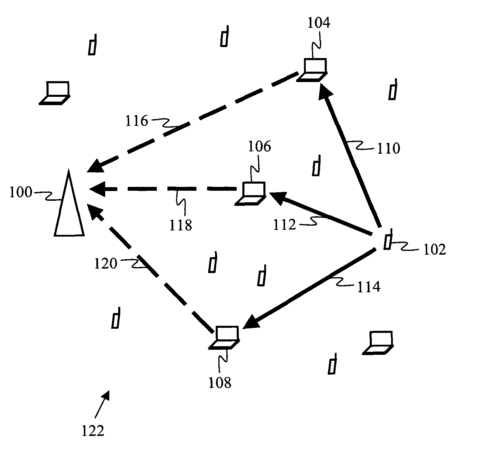
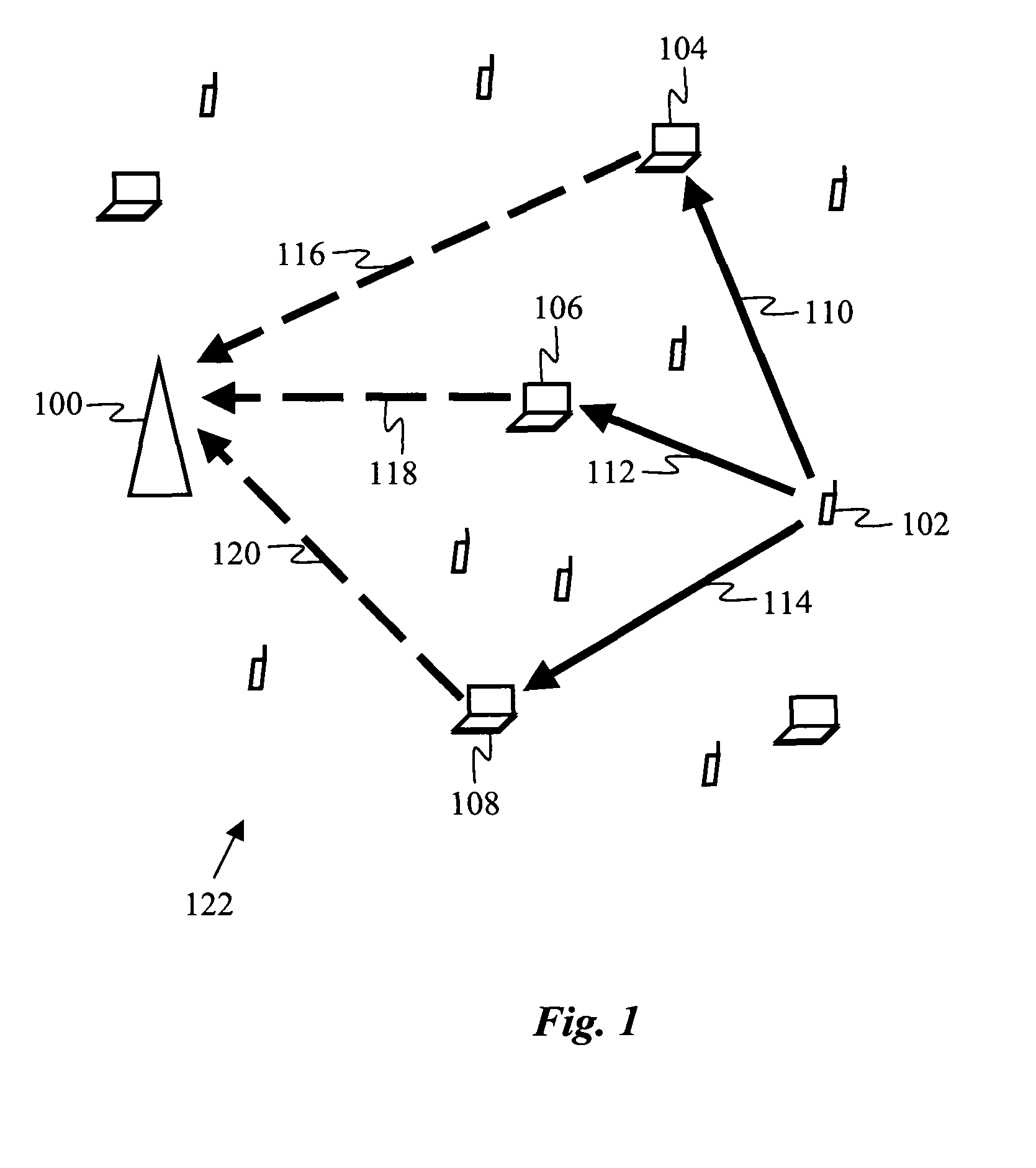
[0020]According to one embodiment of the invention, a method for wireless communication is provided for a dense wireless network, i.e., a network in which a majority of pairs of devices in the network have other devices positioned in the space between them, and in which the nearest neighbor separation between devices in the network is less than 50 meters. An example of such a dense network is a local area network or personal area network containing ten or more devices, such as the network 122 shown in FIG. 1. The network 122 contains various mobile wireless devices, such as devices 102, 104, 106, 108, as well as one or more stationary wireless devices, such as device 100. The mobile devices are typically power-limited, e.g., battery-powered devices such as laptops, PDAs, cell phones, or other hand-held devices, while the stationary devices are typically devices with superior power supplies, e.g., wireless LAN access points or desktop computers with wired infrastructure power. The po...


PUM


Abstract

A method for wireless communication combines OFDMA resource allocation and power control policies with cooperative relaying techniques. The techniques are preferably implemented in a dense wireless network of power-limited mobile devices assisted by mobile relay devices having superior power supplies. Preferably, MIMO beamforming techniques are used to further increase energy efficiency and spectral efficiency beyond the increases provided by ODFMA cooperative relaying.

Description

CROSS-REFERENCE TO RELATED APPLICATIONS[0001]This application claims priority from U.S. Provisional Patent Application 60 / 897,320 filed Jan. 24, 2007, which is incorporated herein by reference.STATEMENT OF GOVERNMENT SPONSORED SUPPORT[0002]This invention was made with Government support under contract DMS-0354674-001 awarded by NSF and contract N00014-02-1-0088 awarded by ONR. The US Government has certain rights in the invention.FIELD OF THE INVENTION[0003]The present invention relates generally to wireless data networks. More specifically, it relates to methods for improving wireless data communications in dense wireless networks.BACKGROUND OF THE INVENTION[0004]A wireless network is a collection of wireless transceivers that communicate over a shared wireless resource in a specified geographic region. Examples are cellular phone networks, wireless local area networks (LANs) and personal area networks (PANs). In the most common networks, a wired base station communicates directly ...

Claims


Application Information

Patent Timeline
Patent Type & Authority Patents(United States)
IPC IPC(8): H04W4/00
CPCH04B7/026H04W52/146H04W52/241H04B7/0617H04B7/0626H04W52/265H04W72/044H04W88/04Y02B60/50
Inventor OYMAN, OZGURPAULRAJ, AROGYASWAMI J.
Owner THE BOARD OF TRUSTEES OF THE LELAND STANFORD JUNIOR UNIV
Why Eureka
Try Eureka