Optical fiber laser, and components for an optical fiber laser, having reduced susceptibility to catastrophic failure under high power operation

a technology components, applied in the direction of cladded optical fibre, optical elements, instruments, etc., can solve the problems of over-the-counter amplifier losses, sudden and unpredictable pulses of backward propagating energy, catastrophic failures of mode field adapters, etc., to reduce the susceptibility of optical fiber lasers or amplifiers to damage, more robust, and more robust

Inactive Publication Date: 2011-09-27
NUFERN
View PDF19 Cites 37 Cited by
  • Summary
  • Abstract
  • Description
  • Claims
  • Application Information

AI Technical Summary

Benefits of technology

[0007]Accordingly, the invention can provide more robust apparatus that can reduce the susceptibility of optical fiber lasers or amplifiers to damage. For example, in one aspect of the invention, there is taught a more robust mode field adapter that is considered less susceptible to catastrophic destruction, as well as, in other aspects, designs and arrangements of fiber based components for making a more robust fiber laser or amplifier. There are many aspects of the invention, which can be practiced alone or in combination. Certain aspects of the invention are described in more detail below.
[0011]In one aspect, the invention provides an optical fiber interconnection apparatus for optically coupling a source of optical energy having an output wavelength and an optical amplifier and having an increased power threshold for avoiding damage to the source or interconnection apparatus from optical energy propagating back from the optical amplifier to the source. The optical fiber interconnection apparatus can comprise an optical fiber arrangement having an input reference plane and an output reference plane and at least one intermediate section of optical fiber having a core spliced at first and second ends, respectively, to the cores of first and second sections of optical fiber. The optical fiber interconnection apparatus can include a first geometrical mismatch and a first numerical aperture mismatch between the core of the intermediate optical fiber and the core of the first section of optical fiber and a second geometrical mismatch and a second numerical aperture mismatch between the core of the intermediate section and the core of the third section of optical fiber. The mismatches can be such that in one direction of propagation, referred to as the forward propagation direction wherein optical energy propagates from an input reference plane to the output reference plane, the geometrical mismatches are from smaller cross sectional area cores to larger cross sectional area cores and the numerical aperture mismatches are from larger numerical aperture cores to smaller numerical aperture cores. In the opposite direction of propagation, wherein optical energy propagates from the output reference plane to the input reference plane, the geometrical mismatches are from larger cross sectional area cores to smaller cross sectional area cores and the numerical aperture mismatches are from smaller numerical aperture cores to larger numerical aperture cores.
[0013]In another aspect, the invention can provide an optical fiber interconnection apparatus for optically coupling a source of optical energy having a selected wavelength and an optical fiber amplifier and having an increased power threshold for avoiding damage to the source or interconnection apparatus from optical energy propagating back from the optical fiber amplifier to the source. The optical fiber interconnection apparatus can comprise an optical fiber arrangement having an input reference location along an input optical fiber and an output reference location along an output optical fiber, the arrangement comprising at least one intermediate section of optical fiber spliced at first and second ends to other optical fibers, there being a geometrical mismatch between the core of the intermediate optical fiber and the cores of each of the other optical fibers. In one direction of propagation, referred to as the forward propagation direction, optical energy propagates from the input reference location to the output reference location and the geometrical mismatches are from smaller cross sectional area to larger cross sectional area cores and in the opposite direction of propagation, referred to as the reverse propagation, the geometrical mismatches are from larger cross sectional area to smaller cross section area cores. The optical insertion loss of the optical fiber arrangement can be non reciprocal in that the insertion loss in the reverse propagation direction is substantially higher than the insertion loss in the forward propagation direction at a wavelength of operation of the optical fiber interconnection apparatus.

Problems solved by technology

Applicant learned that the mode field adapter can suffer catastrophic failures during operation of such high power optical fiber MOPA apparatus.
The backward propagating energy can be a sudden and unpredictable pulse.
Such rogue pulses generally result when the gain of the amplifier, which is function of the inversion of the active material of the amplifier and other factors, such as spurious feedback, exceeds the losses of the amplifier.
A rogue pulse could occur upon temporary failure of a master oscillator (MO) to provide a seed signal, as the lack of seed signal would lead to high inversion.
Although rogue pulses can be caused by a MO failure, perhaps causing a mode field adapter to fail, it is understood that they could also be the cause of MO failure.

Method used


Image

  • Optical fiber laser, and components for an optical fiber laser, having reduced susceptibility to catastrophic failure under high power operation
  • Optical fiber laser, and components for an optical fiber laser, having reduced susceptibility to catastrophic failure under high power operation
  • Optical fiber laser, and components for an optical fiber laser, having reduced susceptibility to catastrophic failure under high power operation

Examples


Embodiment Construction

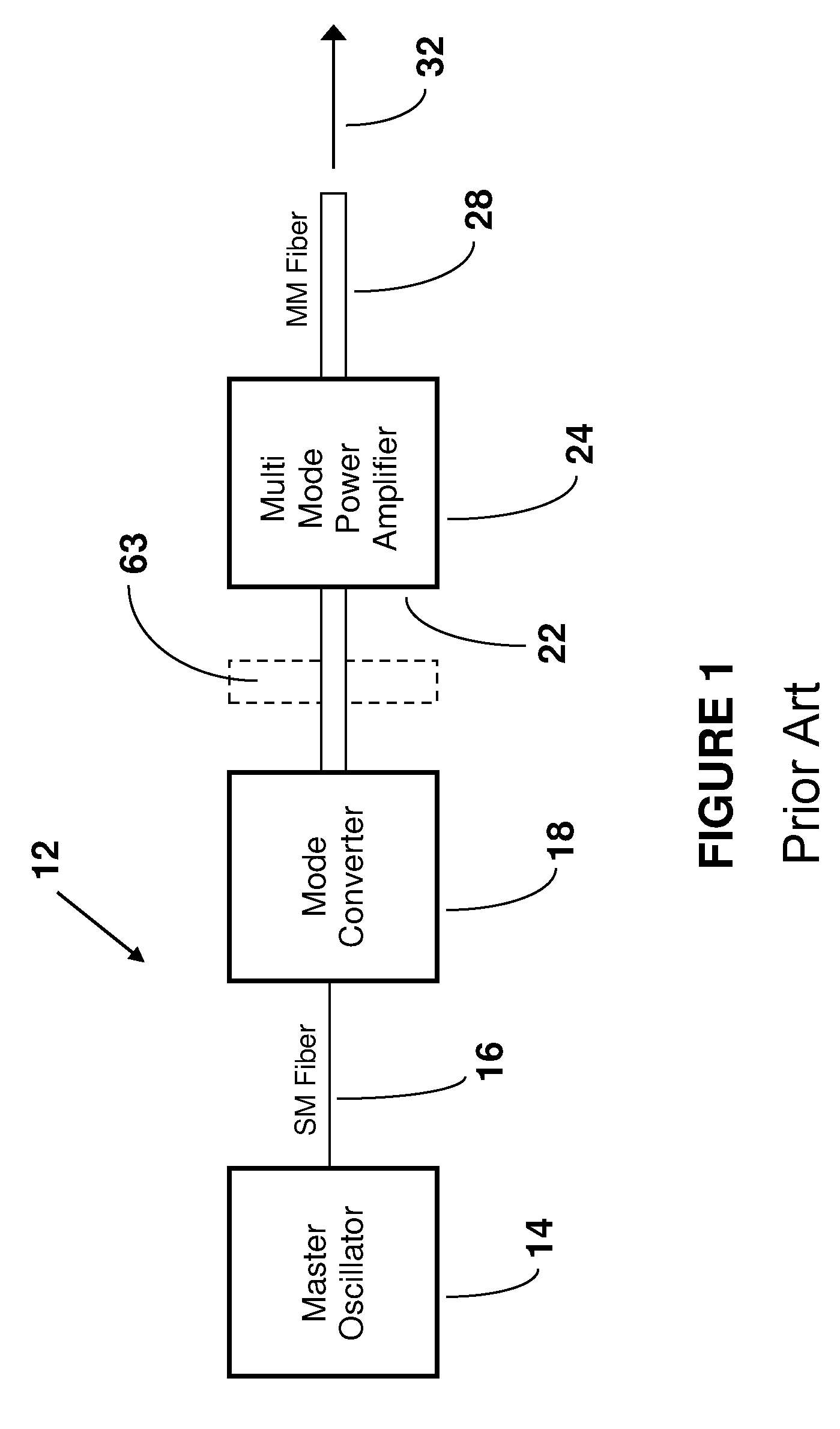
[0032]FIG. 1 schematically illustrates one example of a prior art optical fiber MOPA apparatus 12. The MO 14 can comprise, for example, a single mode (SM) fiber laser that includes a pair of Fiber Bragg Gratings (FBGs) that define a laser cavity for generating the output of the MO 14. The length of SM fiber 16 delivers the output from the laser cavity to the mode converter 18. Accordingly, the MO 14 can provide a SM (e.g., diffraction limited) input beam along the SM fiber 16 to the mode converter 18. The input beam is thus in the fundamental mode and has a small diameter modal profile. The mode converter 18 receives the input beam and converts the fundamental mode of the input beam to match the modal profile of the fundamental mode of the optical fiber multimode (MM) power amplifier 24. The fundamental mode of the MM power amplifier 24 has a different modal profile, such as by at least having a larger diameter than the modal profile of the SM input beam delivered by fiber 16 to the...


PUM


Abstract

Optical fiber lasers and components for optical fiber laser. An optical fiber laser can comprise a fiber laser cavity having a wavelength of operation at which the cavity provides output light, the cavity including optical fiber that guides light having the wavelength of operation, the fiber having first and second lengths, the first length having a core having a V-number at the wavelength of operation and a numerical aperture, the second length having a core that is multimode at the wavelength of operation and that has a V-number that is greater than the V-number of the core of the first length optical fiber at the wavelength of operation and a numerical aperture that is less than the numerical aperture of the core of the first length of optical fiber. At least one of the lengths comprises an active material that can provide light having the wavelength of operation via stimulated emission responsive to the optical fiber receiving pump light. Components include a mode field adapter and optical fiber interconnection apparatus, which can be used to couple the first and second lengths of optical fiber, or can couple the fiber laser to an optical fiber power amplifier, which can be a multimode or single mode amplifier.

Description

FIELD OF THE INVENTION[0001]The present invention relates to optical fiber lasers and optical fiber components therefore, having reduced susceptibility to catastrophic failure under high power operation.BACKGROUND[0002]Optical fiber devices, such as optical fiber lasers and amplifiers, that can provide high output power as well as high beam quality, are of considerable commercial and academic interest. For example, optical fiber lasers that provide a low M2 (a measure of beam quality) and continuous wave (CW) output powers in the range of tens to hundreds or even thousands of Watts have many industrial applications, as do pulsed lasers having good beam quality and high peak powers. In a fiber lasers having a “master oscillator-power amplifier” (MOPA) architecture, a low power laser source (the “master oscillator”) provides an input “seed” beam to an optical fiber amplifier (the “power amplifier”) that amplifies the seed beam. Unfortunately, nonlinear phenomena, such as Stimulated Ra...

Claims


Application Information

Patent Timeline
Patent Type & Authority Patents(United States)
IPC IPC(8): G02B6/26G02B6/36G02B6/02
CPCG02B6/14G02B6/4206G02B6/4296H01S3/005H01S3/06708H01S3/0675H01S3/2308
Inventor FRITH, GAVIN P.
Owner NUFERN
Why Eureka
Try Eureka