Thwartable bottom link for vertical line

a technology of vertical line and bottom link, which is applied in the field of thwartable bottom link for vertical line, can solve the problems of adversely affecting the commercial fishing industry, undesired outcomes, and the inability to keep traps coupled to their associated surface buoys or other markers through vertical lines, and achieves simple but effective effects

Active Publication Date: 2011-10-04
SCHROCK EDWIN B +1
View PDF50 Cites 11 Cited by
  • Summary
  • Abstract
  • Description
  • Claims
  • Application Information

AI Technical Summary

Benefits of technology

[0013]The present invention is designed to overcome the deficiencies of the prior art discussed above. It is an object of the present invention

Problems solved by technology

Unfortunately, the commercial interest in keeping the traps coupled to their associated surface buoys or other markers through vertical lines can run counter to environmental interest.
In particular, it is known that whales, such as the endangered right whale, come in contact with vertical lines and other man-made components of fishing equipment, occasionally with undesired outcomes.
Either option would adversely impact the commercial fishing industry, without the certainty of solving the problem.
That is, the mechanism of whale entanglement with fishing equipment is unclear and therefore the existing proposed solutions may not achieve the desired goal.
First, when they encounter such obstacles, they may move in the direction of the obstacle, such as upward along a lobster vertical line.
As the whale moves, pulling the entire connected underwater structure with it, it likely thrashes about, becoming further entangled.
This entanglement may trap the whale underwater where it drowns.
The first problem is that the tension created by reeling the line in is similar t

Method used


Image

  • Thwartable bottom link for vertical line
  • Thwartable bottom link for vertical line
  • Thwartable bottom link for vertical line

Examples


Embodiment Construction

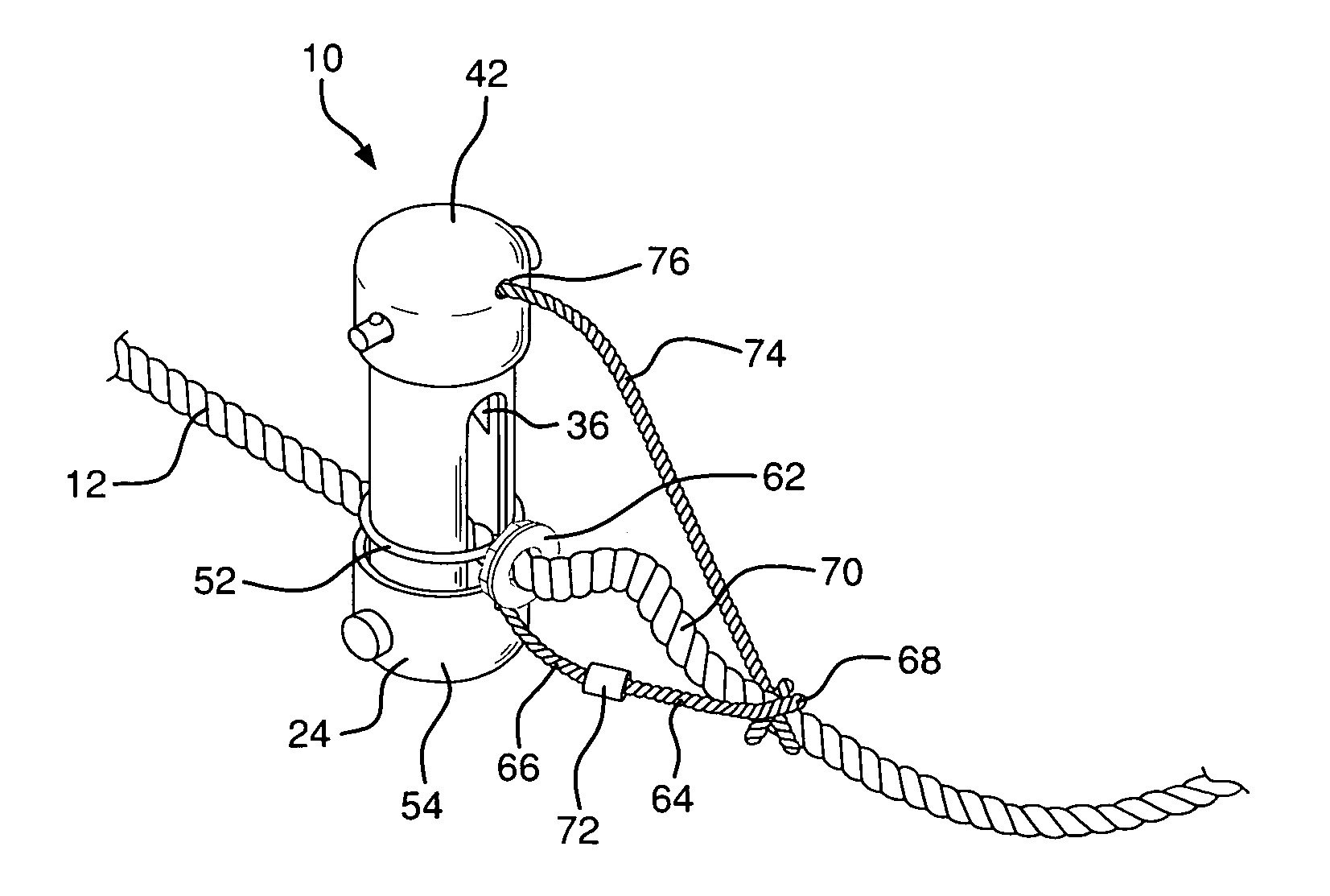
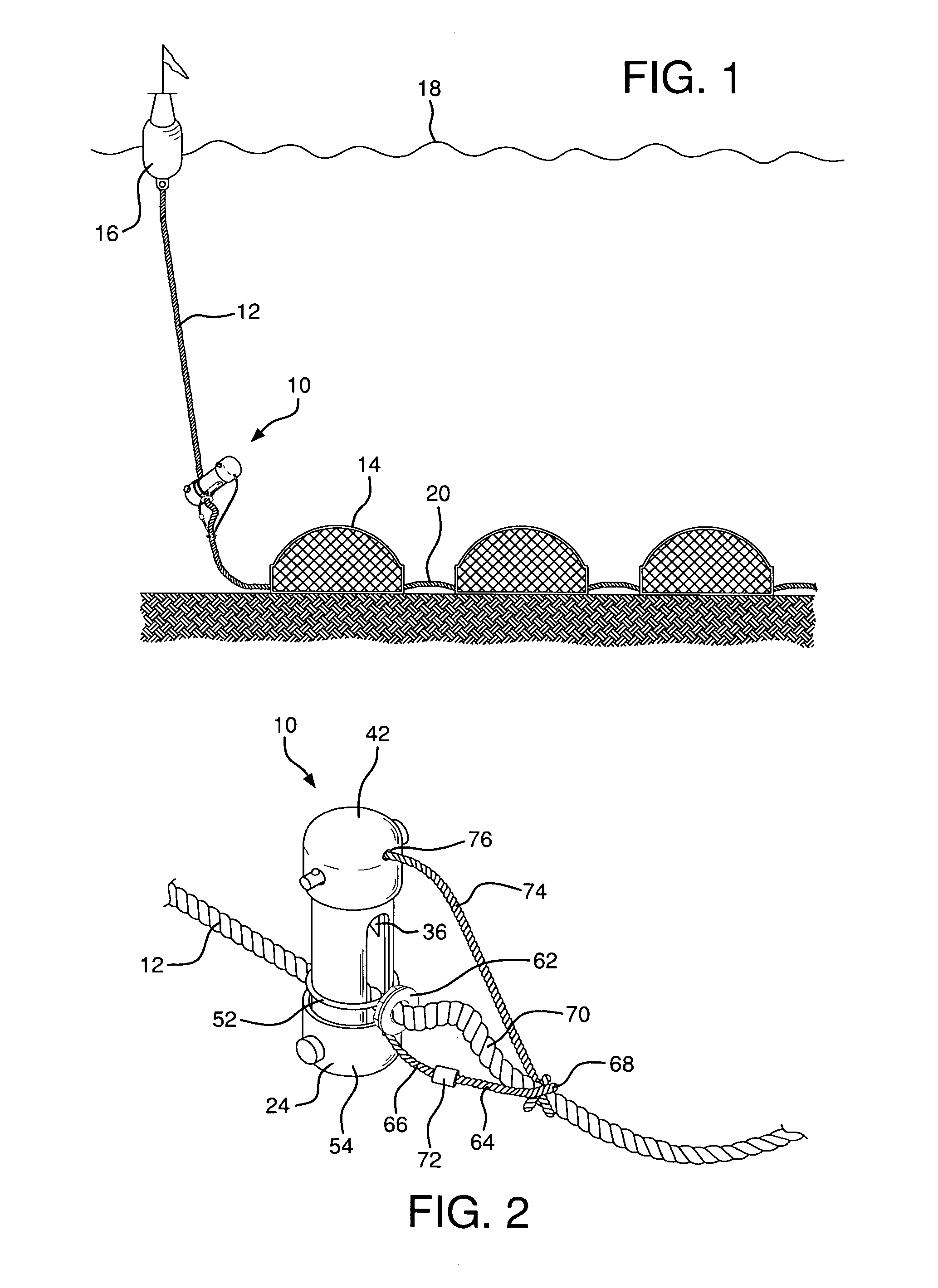
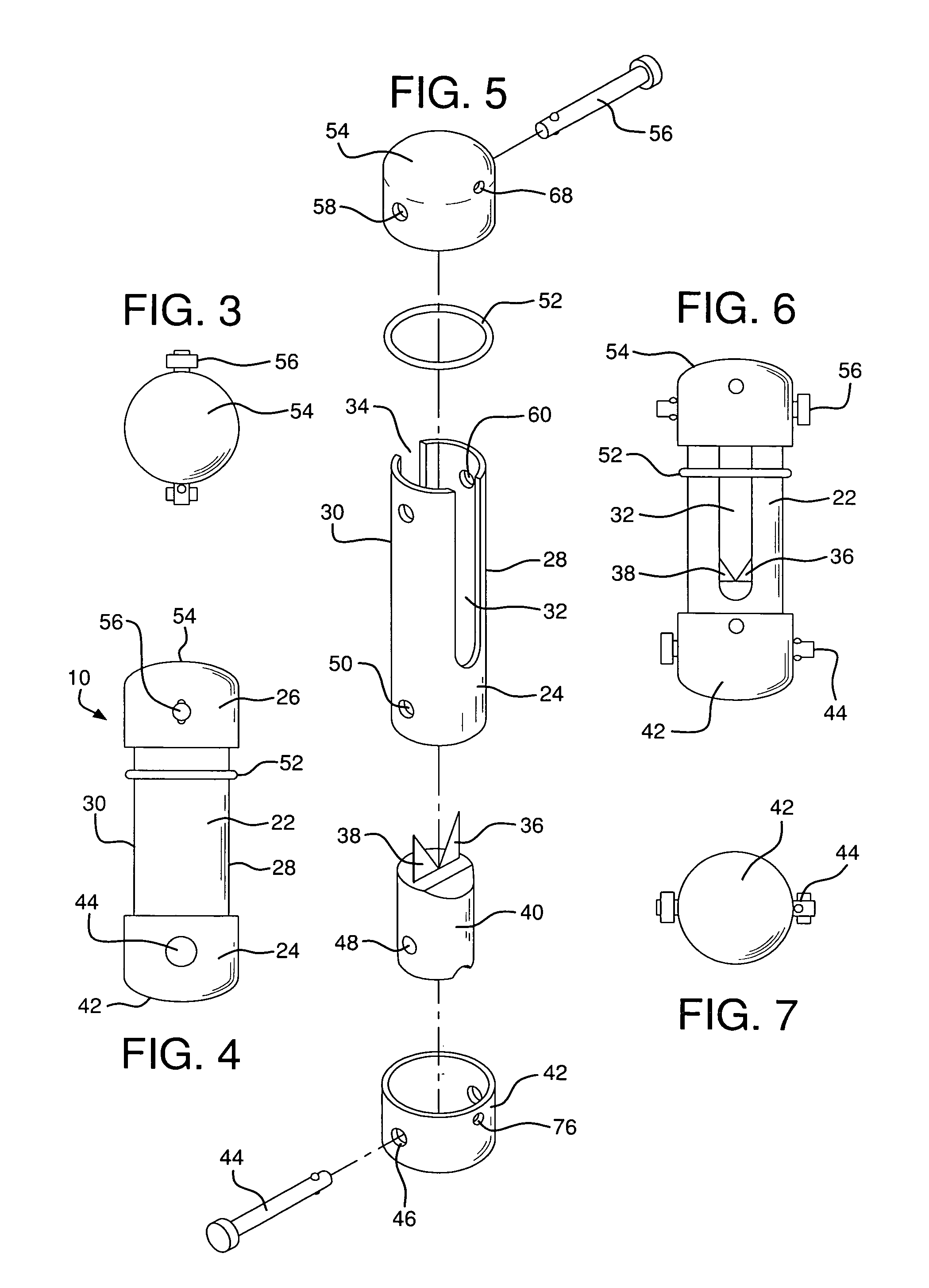
[0027]Referring now to the drawings in detail wherein like reference numerals have been used throughout the various figures to designate like elements, there is shown in FIGS. 1 and 2 a thwartable link for a vertical line constructed in accordance with the principles of the present invention and designated generally as 10. FIG. 1 shows the link 10 in use in the ocean while FIG. 2 is a perspective view of the link connected to a vertical line.

[0028]As shown in FIG. 1, the link 10 of the present invention is connected to the lower end of a vertical line 12 that extends from one end of a series of lobster traps 14 to a buoy 16 floating on the surface of the ocean 18. Although only three lobster traps 14 are shown in FIG. 1, it should be readily apparent that there are normally a significant number of traps that are employed and they are connected in series through ropes 20. Depending on location, the length of the vertical line 12 may be one hundred feet or may be several hundred feet ...


PUM


Abstract

A thwartable link for a vertical fishing line includes a substantially tubularly shaped body having a first end and a second end and first and second opposed side walls extending between the first and second ends. Each of the side walls has an axially extending elongated slot passing therethrough. A knife blade is located within the interior of the tubular body adjacent the first end but facing the second end. The fishing line extends through the slots in the side walls and through the interior of the tubular body. A stop is attached to the line adjacent the first side of the tubular body preventing the line from being pulled through the elongated slot in the first side. A tether extends between the second end of the tubular body and the line. The tether is connected to the line on the same side as the stop means but is spaced therefrom. An elastic O-ring surrounding the tubular body temporarily retains the line adjacent the second end of the tubular member. Applying a tensioning force on the line on the second side of the body causes the line to slide axially in the slots toward the knife blade to be severed by the knife blade. A time release device in the tether disconnects the tether from the tubular member after a pre-selected period of time.

Description

BACKGROUND OF THE INVENTION[0001]The present invention is directed toward a thwartable link for a vertical line and more particularly, toward a thwartable or breakaway link that severs a vertical line from a series of lobster traps in order to prevent injury to a whale that may come in contact with the line.[0002]In the commercial lobstering business, it is common practice to connect a plurality of lobster traps together utilizing a series of ropes. The lobster traps are baited, dropped to the bottom of the seabed from a fishing boat and left for several days before they are retrieved by the lobster fishermen. The position of the traps at sea is marked by a buoy connected by a rope to the first trap in the series. This rope, commonly referred to as a vertical line extends vertically upwardly from the trap to the buoy which may be a distance of one to several hundred feet. Alternatively, two buoys are sometimes used that are spaced apart from each other with the first buoy tied to th...

Claims


Application Information

Patent Timeline
IPC IPC(8): A01K69/06A01K69/08A01K97/00A01K69/00
CPCA01K69/00A01K75/00
Inventor SCHROCK, EDWIN B.SCHROCK, MARILYN L.
Owner SCHROCK EDWIN B
Why Eureka
Try Eureka