Projection type image display apparatus

a technology of projection and display apparatus, which is applied in the direction of lighting and heating apparatus, printing, instruments, etc., can solve the problems of cooling air not fully regulating the cooling air cannot fully regulate the temperature of such arc tubes, and the failure of cooling air to adjust itsel

Inactive Publication Date: 2011-10-04
SANYO ELECTRIC CO LTD
View PDF4 Cites 6 Cited by
  • Summary
  • Abstract
  • Description
  • Claims
  • Application Information

AI Technical Summary

Benefits of technology

[0008]To alleviate the prior art problems as mentioned above, the present invention provides a projection type image display apparatus equipped with a low-cost light source unit capable of circulating cooling air uniformly in the entire reflector element of the light source unit without stagnation, whereby the temperature of the arc tube can be easily regulated, thereby allowing the light source unit to be installed at an arbitrary angular position.
[0014]In this arrangement, since the air inlet port adjacent the opening is formed in one side of the reflector and the other said facing the opening is closed, and since the end of the reflector opposite the opening is closed, the cooling air taken in from the air inlet port flows past the leading end of the arc tube, hits the closed end of the reflector, and, after directed to the outlet ports in the opposing sides, gets exhausted therefrom. Therefore, cooling air can be uniformly circulated in the entire reflector without causing stagnation to regulate the temperature of the arc tube in an easy and costless manner, ensuring good cooling effect on the leading end as well as the light emitting part of the arc tube and on the reflector's opening region, which enables installation of the light source unit at an arbitrary angular position, free of angular limitation.
[0016]In this arrangement, each of the air outlet ports is located at a position intermediate the inlet port and the closed side of the reflector. As a consequence, the cooling air will circulate through the entire region of the reflector without stagnation.

Problems solved by technology

Moreover, it is necessary to regulate the temperature of the arc tube within an appropriate temperature range, since the full performance of the arc tube cannot be elicited if its temperature is too high or too low.
However, in the conventional (i.e. commonly used) arrangements, cooling air fails to circulate round the entire arc tube, so that when the light source unit is installed at an arbitrary angular position, cooling air fails to adjust itself to cool the lowest temperature section that has shifted, that is, cooling air cannot fully regulate the temperature of such arc tube.
Consequently, the arc tube is permitted to have only limited angular positions on account of the poor temperature controllability.
Moreover, the prior art light source unit as disclosed in the cited literature not only requires a blast nozzle, which in turn requires an extra cost therefor, but also complicates the configuration of the light source unit.
In addition, since the blast nozzle is normally designed to blow air only to the upper section of the light source unit, it limits the range of the allowable angular positions of the arc tube

Method used


Image

  • Projection type image display apparatus
  • Projection type image display apparatus
  • Projection type image display apparatus

Examples


Embodiment Construction

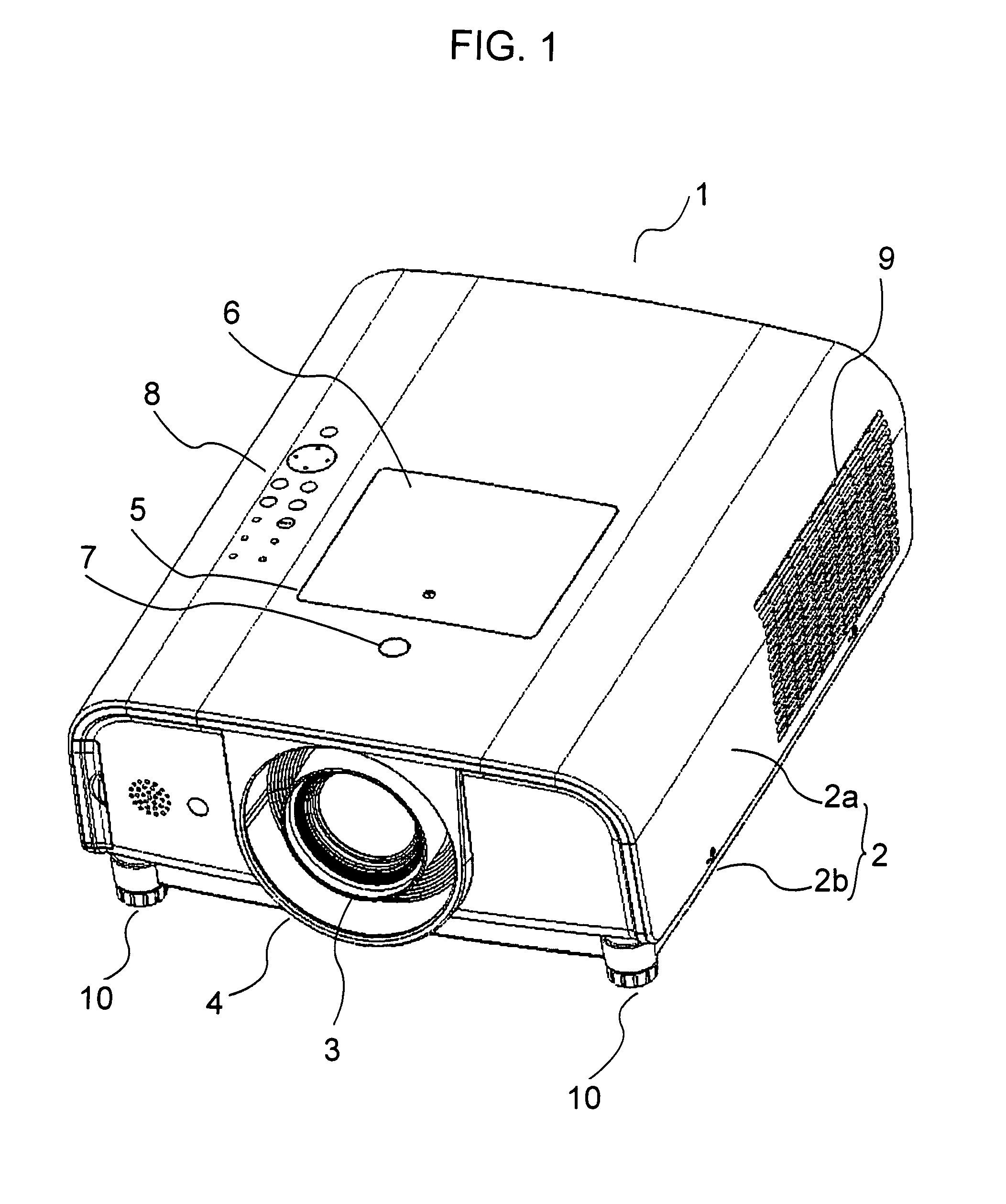
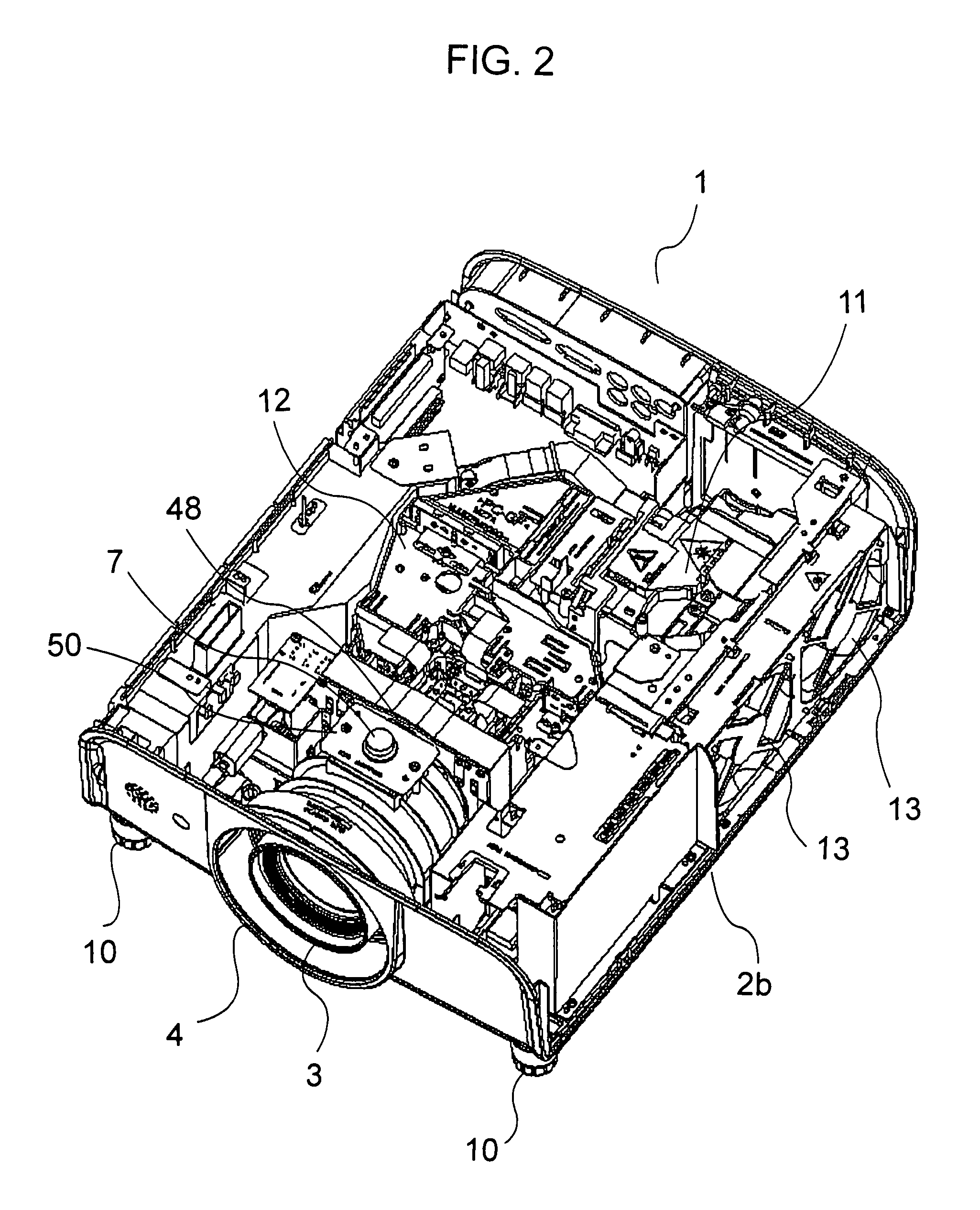
[0038]The invention will now be described in detail by way of example with reference to the accompanying drawings. Referring to FIG. 1, there is shown in oblique perspective view a projection type image display apparatus in the form of a liquid crystal projector in accordance with one embodiment of the invention. FIG. 2 is an oblique perspective view of the projector with its upper case removed.

[0039]As seen in FIG. 1, this liquid crystal projector 1 has a casing 2 which consists of an upper casing 2a and a lower casing 2b. The internal structure of the projector will appear when the upper casing 2a is removed, as shown in FIG. 2.

[0040]There is provided at the center of the front end of the casing 2 a projection window 4 where a projection lens 3 is exposed. Formed in the central area of the upper end of the casing 2 is a maintenance opening 5 and a lid 6 for closing the opening 5 as needed. There are also provided in front of the maintenance opening 5 a projection lens removal butt...


PUM


Abstract

A projection type image display apparatus has a light source unit (11) that includes an arc tube (110) enclosed by a reflector (111) for reflecting the light emitted from the arc tube in one direction through its opening (111a). The opening (111a) of the reflector (111) of the light source unit (11) is covered with a transparent member (112). Formed in one side of the reflector (111), adjacent the opening is an air inlet port (113), while the side facing the air inlet port (113) is closed (i.e. has no port). Formed in the remaining two sides of the reflector (111), and adjacent the opening (111a), are air outlet ports (114) one for each side. This arrangement causes the cooling air to be uniformly circulated in the entire reflector (111) of the light source unit (11) without stagnation to regulate the temperature of the arc tube (110) in an easy and costless manner, and enables installation of the light source unit (11) at any angular position, free of angular limitation.

Description

FIELD OF THE INVENTION[0001]This invention relates to a projection type image display apparatus, and more particularly, to a cooling technology for use with a light source unit of a projection type image display apparatus.BACKGROUND OF THE INVENTION[0002]Projection type image display apparatuses such as a liquid crystal projector use a light source unit which includes a high-intensity arc tube operable at a high temperature, such as a high-pressure mercury lamp or a metal halide lamp, enclosed by a reflector having a parabolic or ellipsoidal reflecting surface for reflecting the light from the arc tube in one direction through a front opening of the reflector. Under a normal operating condition, i.e. when the projector is installed on the level, there will be a temperature gradient inside the reflector such that the temperature is higher in the upper section of the reflector than in the lower section. Therefore, the arc tube is normally designed in such a way that its upper section ...

Claims


Application Information

Patent Timeline
Patent Type & Authority Patents(United States)
IPC IPC(8): B60Q3/04F21V29/505
CPCG03B5/00F21V29/83G03B21/16G03B21/14F21V29/02H01J61/52G03B21/2026G03B21/145
Inventor YAMAMOTO, SEIJIKITANI, TAMAMIYOSHIMURA, TAICHI
Owner SANYO ELECTRIC CO LTD
Why Eureka
Try Eureka