Connection unit and mounting process for such a connection unit

a technology of connection unit and mounting process, which is applied in the direction of electrically conductive connection, coupling device connection, contact member assembly/disassembly, etc., can solve the problems of difficult removal, or impossible, and achieve the effect of facilitating automation

Inactive Publication Date: 2011-10-04
SOURIAU
View PDF13 Cites 9 Cited by
  • Summary
  • Abstract
  • Description
  • Claims
  • Application Information

AI Technical Summary

Benefits of technology

[0011]Thus, when a forced-mounting contact is received in the insert, both parts of the insert are maintained together in position because of the presence of this contact. The contact is forced into the back part of the insert in an almost irreversible manner, whereas the front part of said insert cannot be removed because, once the contact is mounted in the insert, the mechanical stop prevents at the same time the contact from going further into the front part of the insert and the front part of the insert from going out of the back part. The contact assembly enables to mechanically maintain the front part and the back part together.
[0012]The assembly of the forced-mounting contact into the insert of the connection unit according to the invention, such as the mutual positioning of both insert parts, can be advantageously automated.

Problems solved by technology

The back portion of these contacts has such a retaining system that said back portion must be forced into the back part of the insert and, once it is forced therein, it is impossible, or at least very difficult, to remove it.

Method used


Image

  • Connection unit and mounting process for such a connection unit
  • Connection unit and mounting process for such a connection unit
  • Connection unit and mounting process for such a connection unit

Examples


Embodiment Construction

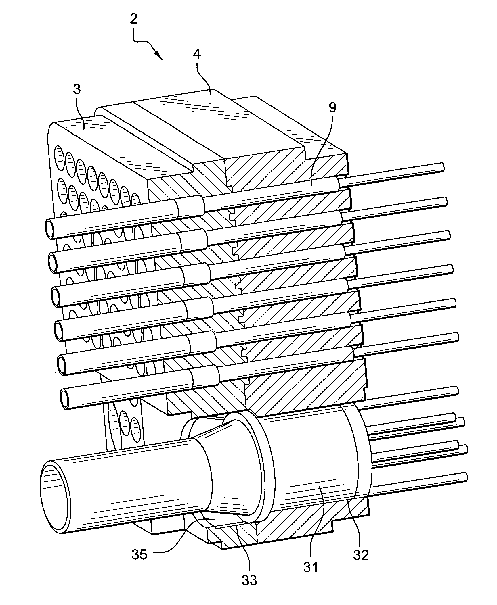
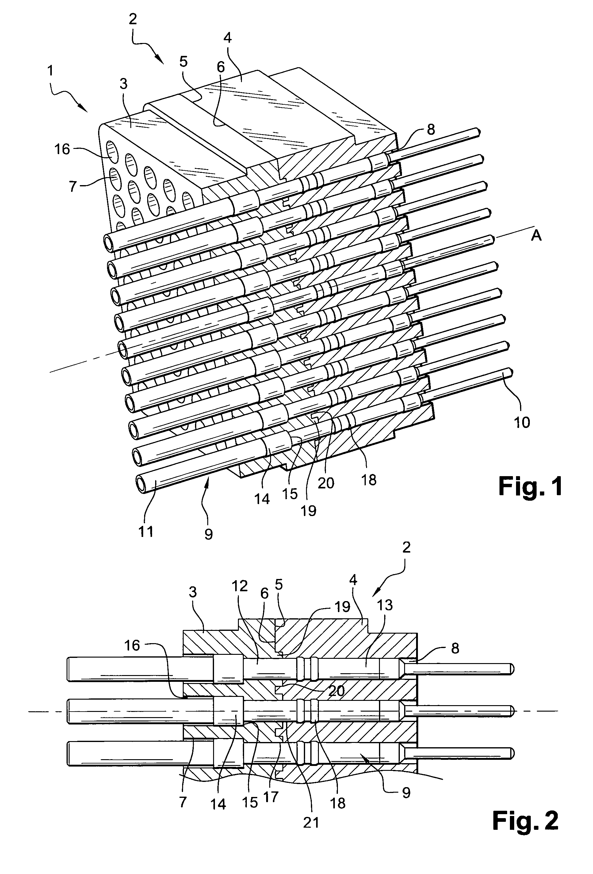
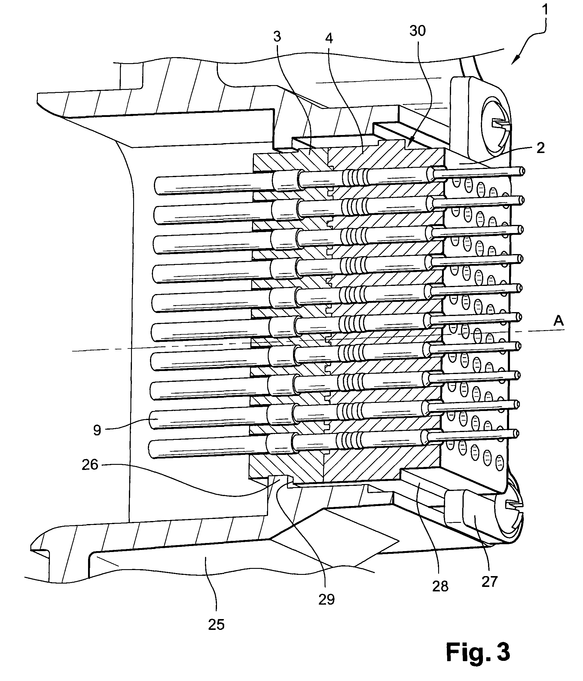
[0053]The connection unit 1 represented in FIGS. 1, 2, 3 and 4 comprises an insert 2 provided with a front part 3 and a back part 4, arranged one to another so that a back side 5 of the front part is placed against a front side 6 of the back part 4.

[0054]In FIGS. 1, 2, 3 and 4, the back elements are on the right side relatively to the front elements placed on the left side.

[0055]The described insert 2 is a right parallelepiped composed of two right parallelepipeds forming the front part 3 and the back part 4 the largest sides of which form the front and back sides of each of both parts 3, 4 of the insert 2.

[0056]Each insert part is provided with a plurality of longitudinal holes 7, 8 which extend parallel to the longitudinal axe A so that they extend right through said insert 2 and open at each of the front and back sides of the involved insert parts 3, 4.

[0057]Each longitudinal through hole 7 in the front part 3 of the insert 2 coincides with a longitudinal through hole 8 in the ba...


PUM

PropertyMeasurementUnit
mechanical behavioraaaaaaaaaa
electricaaaaaaaaaa
contact densityaaaaaaaaaa

Abstract

The invention relates a connection unit comprising an insert provided a front part and a back part provided with longitudinal through holes. At least one longitudinal through hole in the front part of the insert coincides with a longitudinal through hole in the back part. The connection unit includes at least one contact extending through a longitudinal through hole in the front part and through a longitudinal through hole in the back part of the insert. A front portion of the contact is provided with a stop pressing on a stop in the longitudinal hole in the front part of the insert. A back portion of said contact is provided with retaining means which require said back portion be forced into the longitudinal hole in the back part of the insert. The invention also relates a mounting process of such a connection unit, as well as a connection kit.

Description

RELATED APPLICATIONS[0001]This application claims priority from French Patent Application No. 08 54807 filed Jul. 15, 2008, which is herein incorporated by reference in its entirety.TECHNICAL FIELD OF THE INVENTION[0002]The invention relates to an electric connection unit comprising an insert formed of two parts, a front part and a back part, respectively, in which the contacts are received. The invention also relates to a mounting process for such a connection unit, as well as a corresponding connection kit.[0003]The invention is implemented in the field of the connector industry and particularly of the aviation industry, notably for printed board connection.BACKGROUND OF THE INVENTION[0004]Connection units are currently known which are provided with an insert having two parts the front or back part of which is provided with metallic or plastic retaining clips for maintaining electric contacts in said insert. Both parts of the insert are generally stuck together for preventing any ...

Claims


Application Information

Patent Timeline
Patent Type & Authority Patents(United States)
IPC IPC(8): H01R13/514
CPCH01R13/41H01R13/422H01R13/426H01R13/5045H01R13/5205H01R43/20H01R13/502Y10T29/49945
Inventor BARDET, LAURENT
Owner SOURIAU
Why Eureka
Try Eureka