Furnace filter indicator

a technology of indicator and filter, applied in auxillary pretreatment, instruments, separation processes, etc., can solve the problems of increasing back pressure, reducing the efficiency of the heat delivery system and the effective heating of the building, increasing the work that must be performed and the energy consumed by the blower or fan uni

Active Publication Date: 2011-10-04
BD TECH PARTNERS
View PDF23 Cites 84 Cited by
  • Summary
  • Abstract
  • Description
  • Claims
  • Application Information

AI Technical Summary

Benefits of technology

[0012]In one aspect, a system for indicating a status of a filter comprises a device for monitoring pressure differential, a transmitter coupled to the device for transmitting a signal related to the pressure differential, a receiver coupled to the transmitter for receiving the signal related to the pressure differential and an indicator coupled to the receiver for indicating status of the filter based on the signal. The transmitter is coupled to a new or preexisting furnace. The transmitter is coupled to pre-existing wires coupling the furnace to the thermostat. Alternatively, the transmitter and the receiver are wirelessly coupled. The device is positioned to detect static air pressure near the filter(s) and a room air pressure. Alternatively, the device is positioned to detect static air pressure on either side of the filter(s). The device is a differential pressure switch. Alternatively, the device is a differential pressure sensor. The indicator includes one or more light emitting diodes. Alternatively, the indicator is a liquid crystal display. The indicator indicates “dirty” after receiving a “dirty” signal from the transmitter. In alternative embodiments, the system further comprises an audible indicator to audibly notify a user to change the filter.
[0013]In another aspect, a system for indicating a status of a furnace filter comprises a pressure differential switch positioned near the furnace filter for monitoring pressure differential, a transmitter coupled to the pressure differential switch for transmitting a signal related to the pressure differential, a receiver coupled to the transmitter for receiving the signal related to the pressure differential and one or more light emitting diode indicators coupled to the receiver for indicating status of the furnace filter based on the signal, wherein the transmitter is coupled to pre-existing wires coupling a furnace to a thermostat. The one or more light emitting diode indicators indicate “dirty” after receiving a “dirty” signal from the transmitter. In alternative embodiments, the system further comprises an audible in

Problems solved by technology

The increased restriction reduces the efficiency of the heat delivery system and the effective heating of the building.
The partially clogged filter also causes increased back pressure to be applied to the blower or fan which generates the air flow in forced air systems and this back pressure increases the work that must be performed and the energy consumed by the blower or fan unit.
The resulting added load increases the wear rate of the moving parts in the heating system and also results in increased operating costs.
Ultimately, a heavily clogged filter can cause the system to stop operating completely, create a fire hazard or fail catastrophically “dumping” the captured particles back into the airstream and into the house.
This procedure has many problems.
This often results in dirty filters

Method used


Image

  • Furnace filter indicator
  • Furnace filter indicator
  • Furnace filter indicator

Examples


Embodiment Construction

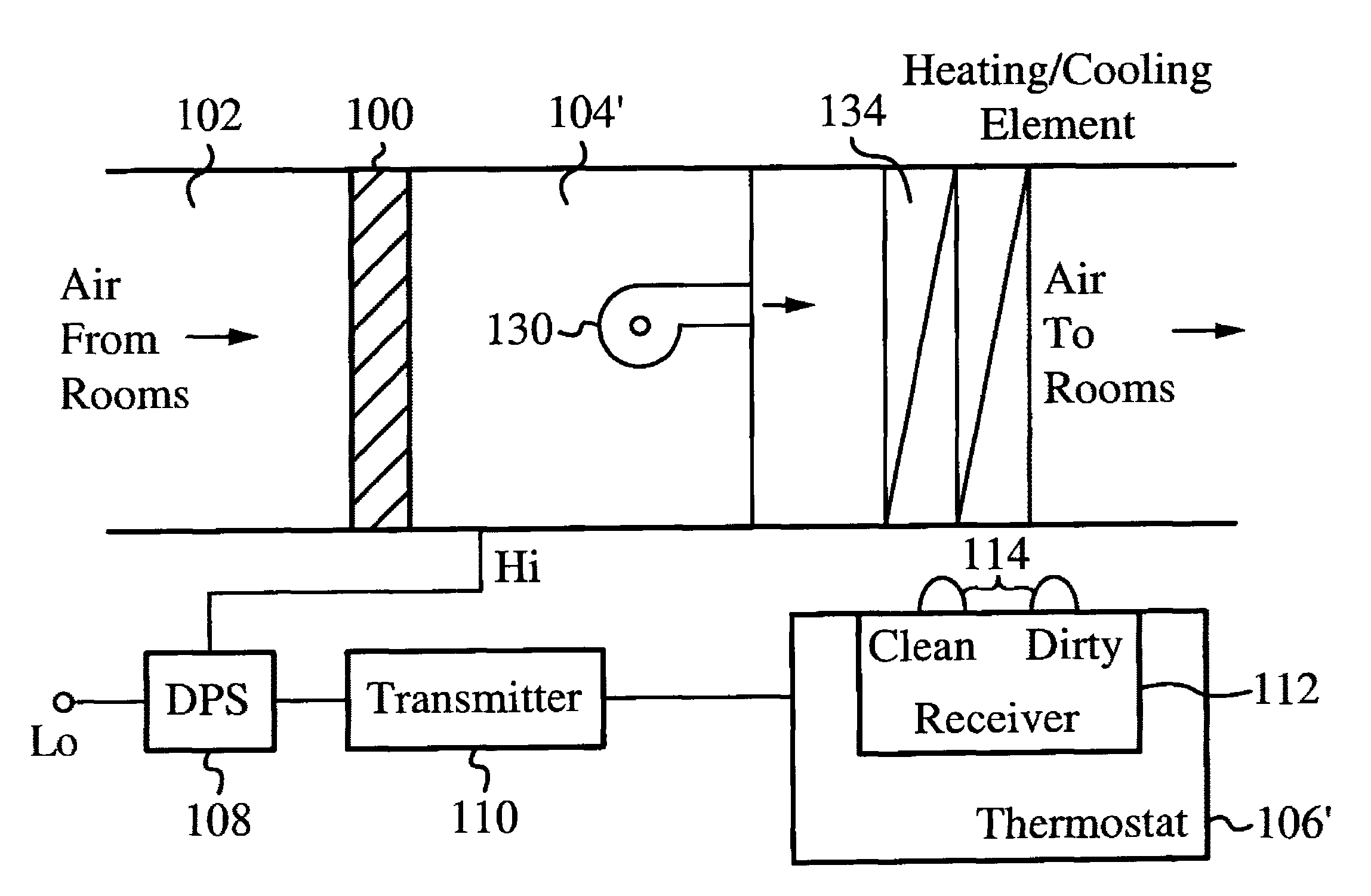
[0022]The present invention is a furnace filter status indicator that provides a remote indication when a furnace filter needs to be replaced. The indicator comprises two main components, a differential pressure switch (DPS) / transmitter located at a filter and an indicator / receiver located with a thermostat. The transmitter and receiver communicate through existing thermostat wiring.

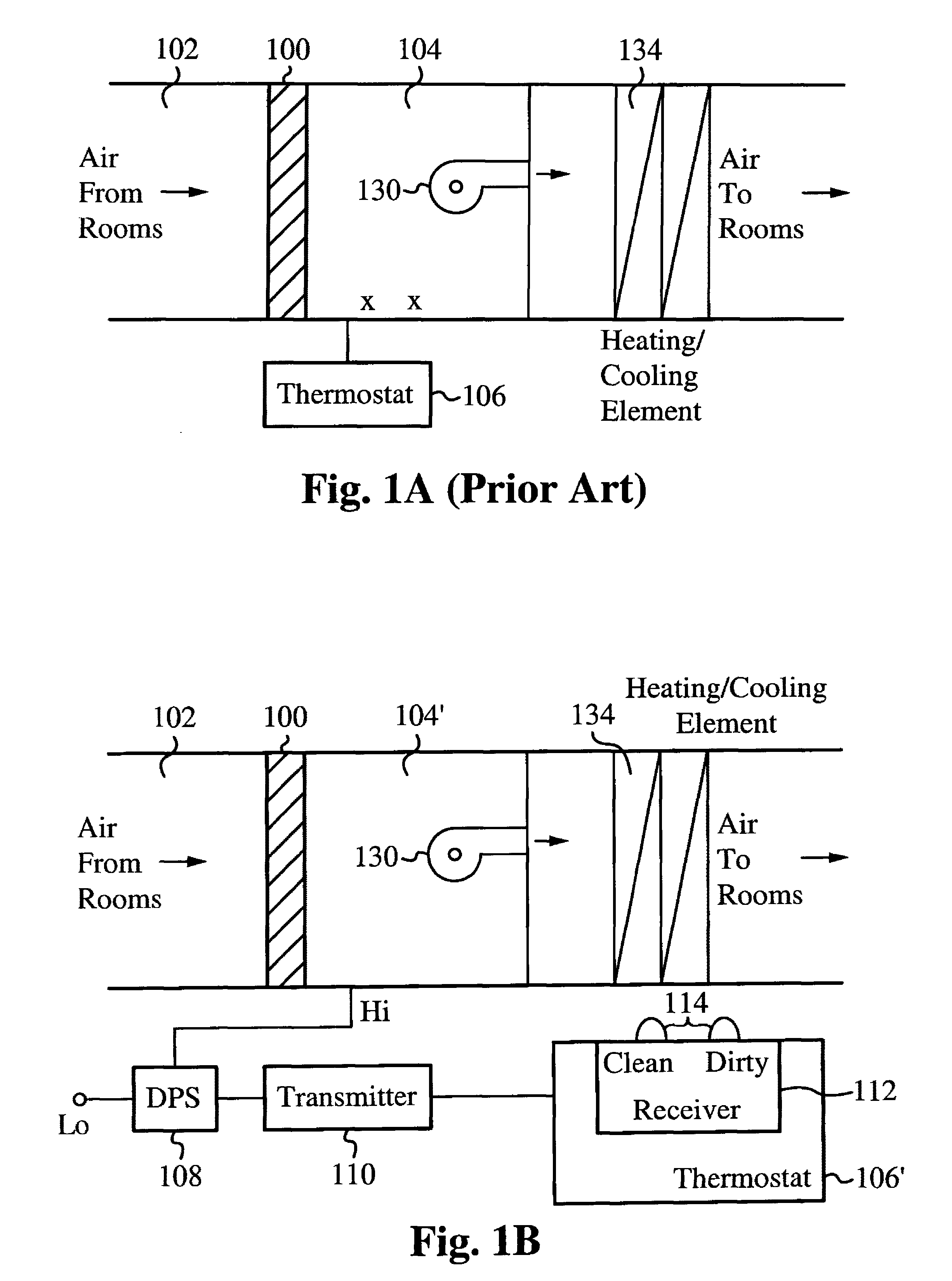
[0023]FIG. 1A illustrates a block diagram of a standard installation of a furnace 104 and a thermostat 106. In the standard installation, the furnace 104 and thermostat 106 are coupled directly together via wires. A fan 130 is utilized to maintain the flow of the air. A heating / cooling element 134 is utilized to heat or cool the air. The heating / cooling element 134 is able to be positioned as shown or closer to the filter 100 or the fan 130 as designated by x. A filter 100 is used as described above to remove particulates from the air as it comes from a heater return air duct 102.

[0024]FIG. 1B illustrate...


PUM

PropertyMeasurementUnit
Pressureaaaaaaaaaa
Frequencyaaaaaaaaaa

Abstract

A furnace filter indicator system comprises a pressure differential switch that monitors air pressure near a furnace filter, and a transmitter coupled to the pressure differential switch sends a signal to a receiver within a thermostat. The receiver includes an indicator for indicating the status of the furnace filter. If the pressure differential near the furnace filter triggers the switch, then the indicator will receive a “dirty” signal and will indicate that the furnace filter is dirty and should be replaced. The furnace filter indicator system is able to be installed on a previously installed furnace/thermostat system by utilizing the pre-existing wiring.

Description

FIELD OF THE INVENTION[0001]The present invention relates to the field of furnace filter diagnostics. More specifically, the present invention relates to the field of remote furnace filter indicators using pre-existing thermostat wiring.BACKGROUND OF THE INVENTION[0002]Systems for delivering heated air include filtration equipment for removing particles from the air. The systems typically include mechanical filters formed from fibrous materials. The filter material functions to block particulate matter that is in the air. Particulate matter becomes attached to the filter material which, over a period of time, progressively restricts the flow of air through the filter.[0003]The increased restriction reduces the efficiency of the heat delivery system and the effective heating of the building. The partially clogged filter also causes increased back pressure to be applied to the blower or fan which generates the air flow in forced air systems and this back pressure increases the work th...

Claims


Application Information

Patent Timeline
IPC IPC(8): B01D49/00
CPCB01D46/0086F24F2011/0042F24F2011/0093F24F2110/40F24F11/39
Inventor BRESLIN, STEWART
Owner BD TECH PARTNERS
Why Eureka
Try Eureka