LED (light emitting diode) backlight driving method, liquid crystal display device and LED backlight driving circuit

A backlight drive circuit and liquid crystal display device technology, applied to lighting devices, lamp circuit layout, light sources, etc., can solve the problems of low power supply efficiency, loss, and temperature rise of constant current control circuits, so as to reduce the pressure difference and improve Efficiency and loss reduction effect

Active Publication Date: 2011-11-16
SHENZHEN CHINA STAR OPTOELECTRONICS TECH CO LTD
View PDF8 Cites 23 Cited by
  • Summary
  • Abstract
  • Description
  • Claims
  • Application Information

AI Technical Summary

Problems solved by technology

In this embodiment, due to the different voltages of LEDs in different strings, the difference will be added to the constant current ...

Method used


Image

  • LED (light emitting diode) backlight driving method, liquid crystal display device and LED backlight driving circuit
  • LED (light emitting diode) backlight driving method, liquid crystal display device and LED backlight driving circuit
  • LED (light emitting diode) backlight driving method, liquid crystal display device and LED backlight driving circuit

Examples


Embodiment 1

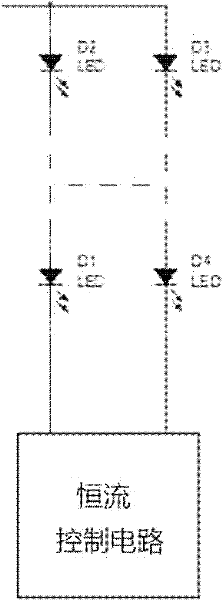
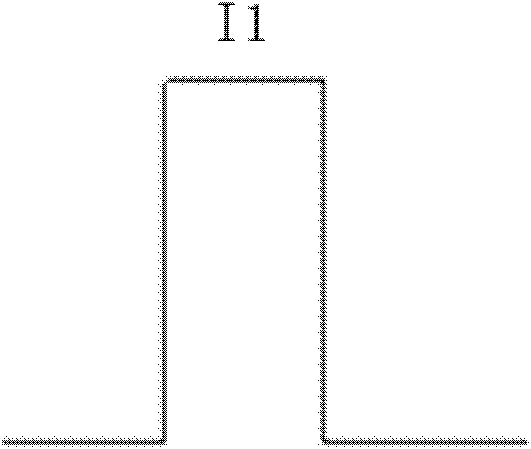
[0035] First execute step A: based on the minimum voltage, detect the voltage value of the LED string 1 with the smallest voltage, and adjust the current of each LED string 1 so that the voltage of each LED string 1 is the above-mentioned voltage value. Step B is then executed: by adjusting the current duty cycle of the corresponding LED string 1 , the effective value of the current of each LED string 1 reaches the preset brightness requirement. In this method, the current duty cycle of the LED string 1 is preferably less than 80%, so as to ensure a wide adjustment range. Based on the minimum voltage value of LED string 1, lower power consumption can be obtained.

[0036] In order to prevent that the brightness of the LED cannot be guaranteed to meet the requirements when the duty cycle is adjusted to the maximum value, the step B may be followed by a step C: feeding back the effective value of the current after the current equalization to the power supply for the LED string 1...

Embodiment 2

[0039] Similarly, step A is executed first, and the step A includes the following steps: detecting the voltage value of the LED string 1 with the highest voltage, and adjusting the current of each LED string 1 so that the voltage of each LED string 1 is the above-mentioned voltage value. Step B is then executed: by adjusting the current duty cycle of the corresponding LED string 1 , the effective value of the current of each LED string 1 reaches the preset brightness requirement. This embodiment is based on the maximum voltage value of the LED string 1 .

[0040]Similarly, in order to ensure that the brightness of the LED meets the requirements, the step B is followed by a step C: feeding back the current effective value after the current equalization to the power supply module that supplies power to the LED string 1, and the power module is effective according to the current required by the current brightness. Adjust the output voltage in real time, and then repeat steps A~C....

Embodiment 3

[0043] Similarly, step A is executed first, and the step A includes the following steps: detecting and calculating the average voltage of each LED string 1 , and adjusting the current of each LED string 1 so that the voltage of each LED string 1 is the above-mentioned average voltage. Step B is then executed: by adjusting the current duty cycle of the corresponding LED string 1 , the effective value of the current of each LED string 1 reaches the preset brightness requirement. In this embodiment, the average voltage of the LED string 1 is used as a reference, and a wide adjustment range can be obtained.

[0044] Similarly, in order to ensure that the brightness of the LED meets the requirements, the step B is followed by a step C: feeding back the current effective value after the current equalization to the power supply module that supplies power to the LED string 1, and the power module is effective according to the current required by the current brightness. Adjust the outp...


PUM


Abstract

The invention discloses an LED (light emitting diode) backlight driving method, a liquid crystal display device and an LED backlight driving circuit. The LED backlight driving method comprises the following steps of: adjusting the size of currents of LED strings so that the voltages of all the LED strings are equal; and adjusting the current duty ratio of the corresponding LED strings so that thecurrent effective value of each LED string reaches the brightness requirement. According to the invention, the voltages of all the LED strings are kept equal through adjusting the size of currents bya current adjustment module, therefore, the problem of loss caused by voltage difference can be solved; the current effective values of all the LED strings are kept equal through adjusting duty ratioof a duty ratio adjustment module, therefore, the brightness consistency is ensured.

Description

technical field [0001] The invention relates to the field of liquid crystal display, and more specifically, relates to an LED backlight driving method, a liquid crystal display device and an LED backlight driving circuit. Background technique [0002] For liquid crystal display devices using LEDs as backlight sources, the existing LED drive devices such as figure 1 As shown: the backlight driver includes a light guide plate, on which there are multiple LED strings connected in parallel, and each LED string includes multiple LED lights in series. Current controller, the LED drive device will monitor the voltage of each LED string in real time, and then feed back the minimum voltage to the input terminal of the power supply, and adjust the value of the forward voltage Vin to ensure that the forward voltage Vin can meet the brightness of the LED string with the minimum voltage Requirements to optimize the input voltage of the LED. At the same time, in order to ensure the cons...

Claims


Application Information

Patent Timeline
IPC IPC(8): G09G3/36
CPCH05B37/00G09G3/342G09G2320/0233G09G2320/064G09G2330/028H05B45/10H05B45/46
Inventor 高新明
Owner SHENZHEN CHINA STAR OPTOELECTRONICS TECH CO LTD
Why Eureka
Try Eureka