PWM (Pulse-Width Modulation) controller

A controller and comparator technology, applied in the power supply field, can solve the problems of increasing system complexity, limiting the application environment, current mode peak current limit drift, etc., to ensure the current limit, improve efficiency, and reduce costs.

Inactive Publication Date: 2012-05-02
UNIV OF ELECTRONICS SCI & TECH OF CHINA
View PDF4 Cites 18 Cited by
  • Summary
  • Abstract
  • Description
  • Claims
  • Application Information

AI Technical Summary

Problems solved by technology

The structure diagram of traditional PWM controller is as follows: figure 1 As shown, the error output signal is directly superimposed with the slope compensation signal to obtain a level that changes with the duty cycle. However, due to the slope compensation, the peak current l

Method used


Image

  • PWM (Pulse-Width Modulation) controller
  • PWM (Pulse-Width Modulation) controller
  • PWM (Pulse-Width Modulation) controller

Examples


Embodiment Construction

[0023] The present invention will be further elaborated below in conjunction with the accompanying drawings and specific embodiments.

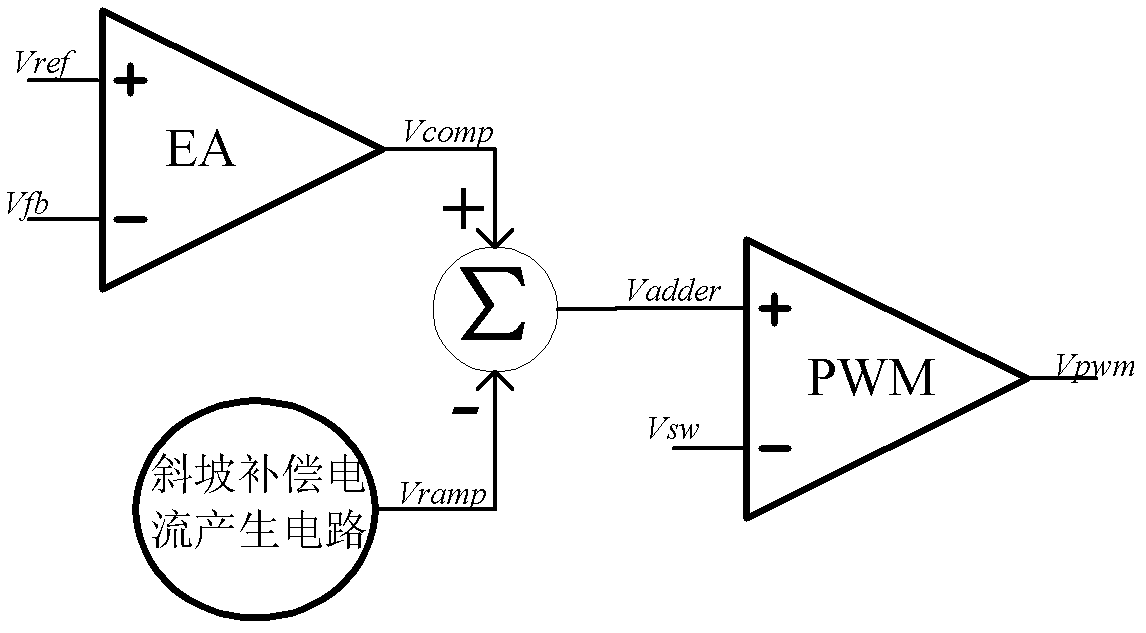
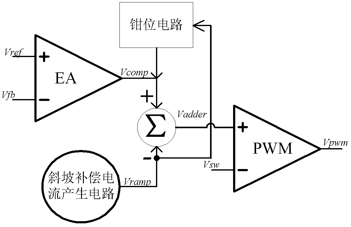
[0024] The structure schematic diagram of PWM controller of the present invention is as figure 2 As shown, it includes an error amplifier EA, a PWM comparator, a slope compensation current generation circuit, a clamp circuit and a slope compensation superposition circuit, wherein the slope compensation current generation circuit is used to convert the slope compensation voltage into a slope compensation current, The positive input terminal of the error amplifier EA is used to input and output the feedback voltage V fb , the negative input terminal is used to input the external reference voltage source V ref ; The clamping circuit is used to make the signal output by the error amplifier follow the slope compensation voltage to change with the same slope, and its input terminal is connected to the output terminal of the slope compensation curr...


PUM


Abstract

The invention discloses a PWM (Pulse-Width Modulation) controller which comprises an error amplifier, a PWN comparator, a slope compensation current generating circuit, a clamping circuit and a slope compensation superposed circuit. In the PWM controller, the clamping circuit is introduced so that a high-end clamping point output by the error amplifier synchronously changes along with a slope compensation signal and an inductance current peak value is maintained to be unchanged, and thus the problem that the duty ratio affects a peak value current limit is solved, a constant current limit is ensured and the whole system works normally; and a relative earth potential concept is introduced by adding a relative earth potential generating circuit into the PWM comparator, so as to reduce voltage difference between power supply voltages, thus a high-performance high-speed PWM controller can be realized by use of low voltage components.

Description

technical field [0001] The invention belongs to the technical field of power supplies, and in particular relates to the design of a PWM controller. Background technique [0002] Switching power supply has been widely used due to its high efficiency, driving large load and small static power consumption. The pulse width modulation (Pulse Width Modulation, PWM) control method is widely used in switching power supply. There is a close relationship between the performance of the controller, so the study of high-performance PWM controller has great theoretical and practical value. [0003] In switching power supplies, voltage mode and current mode are two commonly used control modes. The current mode is widely used for its fast response, high stability, and cycle-by-cycle current limit. The structure diagram of traditional PWM controller is as follows: figure 1 As shown, the error output signal is directly superimposed with the slope compensation signal to obtain a level that ...

Claims


Application Information

Patent Timeline
IPC IPC(8): H03K7/08
Inventor 周泽坤黄建刚王慧芳石跃明鑫张波
Owner UNIV OF ELECTRONICS SCI & TECH OF CHINA
Why Eureka
Try Eureka