
Method and device for shaping of composite material

a composite material and shaping technology, applied in dough shaping, manufacturing tools, other domestic objects, etc., can solve the problems of material not closely following the contour of the forming tool as the material forms, the pressure of the vacuum foil is too low, and the problem is even larger for heavy blanks, so as to achieve the effect of less manual labor

Inactive Publication Date: 2011-10-04
SAAB AB
View PDF10 Cites 4 Cited by
  • Summary
  • Abstract
  • Description
  • Claims
  • Application Information

AI Technical Summary

Benefits of technology

The invention is a method and device for shaping composite materials, such as beams for aircraft assemblies, using a forming tool and an air-tight foil. The method involves arranging a blank of composite material on the tool, supporting it with several support means, and then shaping the blank over the tool to match its form. The device includes a forming tool and an air-tight foil, along with several support means that are arranged to support the blank. The support means can be raised and lowered in a controlled manner, allowing for easy shaping of the blank over the tool. The resulting article closely matches the shape of the tool, and the method is fast, simple, and cost-effective with minimal manual labor.

Problems solved by technology

When using the aforementioned method for shaping of complex composite articles, such as elongated C-shaped beams with longitudinal flanges, a common problem is that the material does not closely follow the contour of the forming tool as the material forms over tool.
This effect is comes due to the fact that the pressure from the vacuum foil is too low at the beginning of the forming process.
The problem is even larger for heavy blanks which tend to self form over the tool due to their own weight at the beginning of the forming process.
A further problem is that creases may arise in the articles, due to friction between fibre layers in the blank as the layers slide on each other during forming of the blank.
The use of manual labour for laying-up and forming the material over the tool is time consuming and involves high costs.
The disadvantage of this solution is that further forming of the article cannot be done, and that the release-sheet itself can be an incitement for the creation of creases in the composite.

Method used


Image

  • Method and device for shaping of composite material
  • Method and device for shaping of composite material
  • Method and device for shaping of composite material

Examples


Embodiment Construction

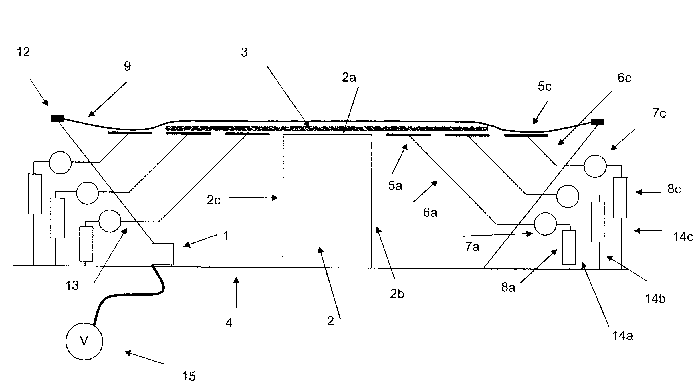
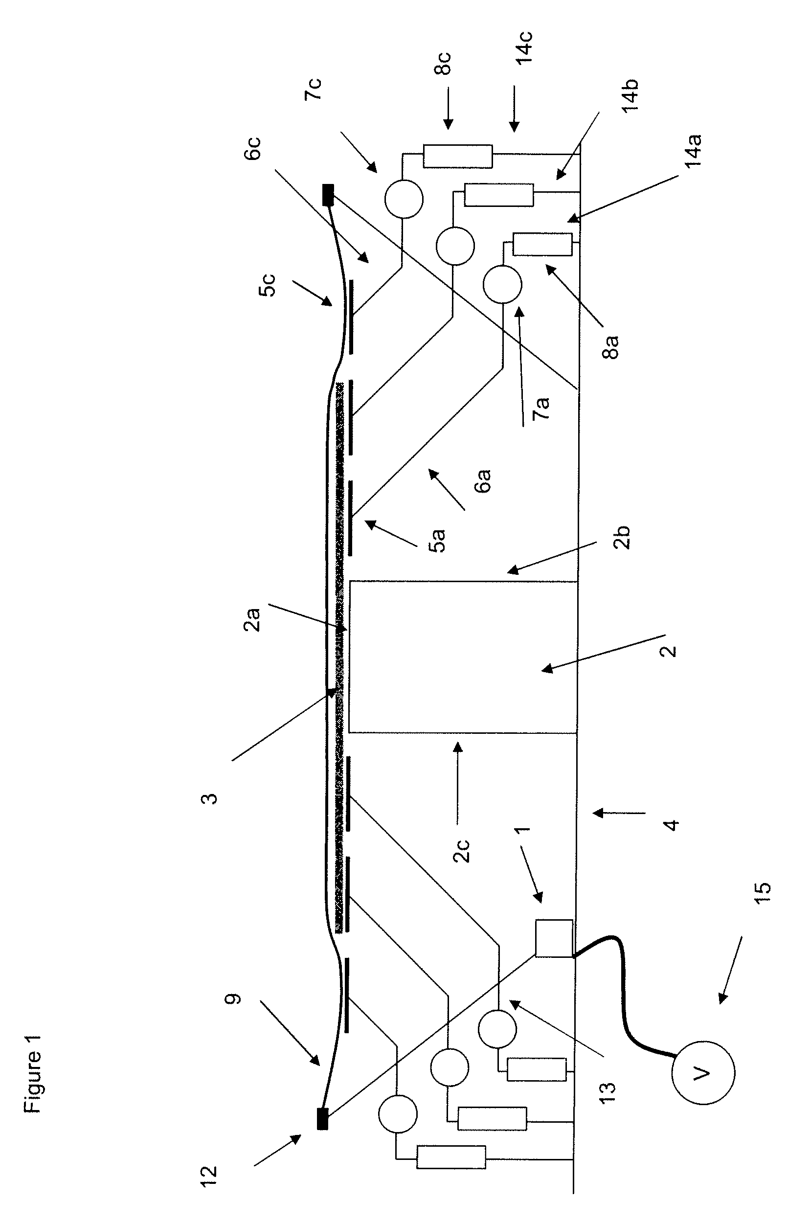
FIG. 1 illustrates a device 1 for shaping a blank 3 of composite material over a tool 2 including a an air-tight foil 9, preferably the shaping is performed by heating the blank to its softening temperature and applying pressure on the blank to force it to form over the tool 2, so called thermoforming.

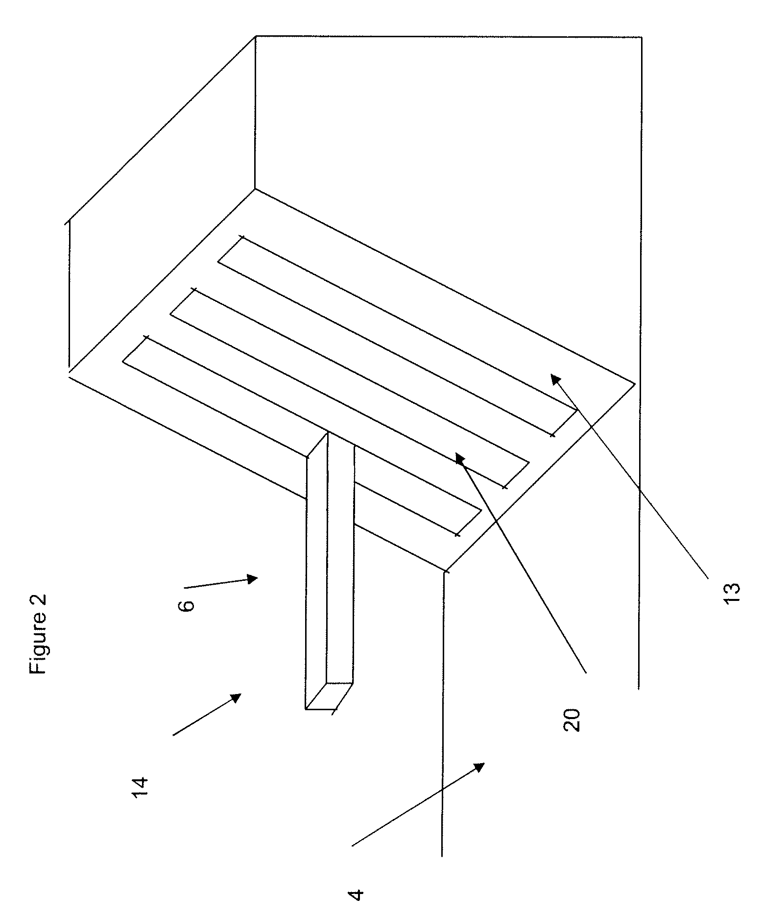
The device 1 according to the invention for shaping an article of composite material comprises a container 21 including a base 4, which is surrounded by an inclined wall 13. The base 4 supports a heatable forming tool 2 having a top surface 2a and side surfaces 2a and 2c. The tool extends in the longitudinal direction of the container 21. The device 1 further includes one or more support arrangements 14a-n each comprising a flat elongated support means 5a-n and an arm 6a-n. The support means 5a-n are arranged on the arms 6a-n. The support arrangements 14a-n further comprises raising / lowering means 8a-n arranged on one end of the arms 6a-n. The raising / lowering means 8a-n could be hydra...


PUM

PropertyMeasurementUnit
distanceaaaaaaaaaa
distanceaaaaaaaaaa
temperatureaaaaaaaaaa

Abstract

A method and device for shaping of an article of composite material. The method includes arranging a blank of composite material on a top surface of a forming tool. A portion of the blank is arranged to protrude outside the top surface of the tool. At least one support is arranged in contact with an underside of the protruding portion of the blank. An air-tight foil is arranged over the arrangement. The air-tight foil is forced towards the blank. The support is lowered until the blank is shaped over the tool. The support is stopped and / or removed. The device includes a tool including a top surface and side surface for shaping at least one blank of composite material into an article having a predetermined profile; and a air-tight foil. The device further includes at least one support arranged to be in supporting contact with the underside of the protruding part of the blank.

Description

CROSS-REFERENCE TO RELATED APPLICATIONSThis application claims priority to European patent application 07118136.9 filed 9 Oct. 2007.FIELD OF THE INVENTIONThe present invention relates to a method and a device for shaping of composite materials e.g. thermoforming.BACKGROUND OF THE INVENTIONShaping of composite materials, such as pre-preg (layers of fibre material previously impregnated with resin), into details is today commonly performed by thermoforming. In thermoforming, a blank of composite material is placed on a forming tool so that a part of the composite material protrudes over the edge of the tool. The tool and the composite material are covered with a vacuum foil, such as a rubber sheet which is sealed air-tight around the tool. The arrangement is heated and the air under the vacuum foil is sucked out. Due to the increased temperature the composite material softens and is shaped over the forming tool by the force exerted by the vacuum foil exerted on the surface of the prot...

Claims


Application Information

Patent Timeline
Patent Type & Authority Patents(United States)
IPC IPC(8): B29C59/02B29D99/00
CPCB29C43/12B29C43/3642B29C53/025B29C70/44Y02T50/433B29C2043/3644B29C53/04Y02T50/40
Inventor PETERSSON, MIKAELWEIDMANN, BJORN
Owner SAAB AB
Learn More