Turbine for driving a generator in a drill string

a generator and drill string technology, applied in the direction of motors, dynamo-electric machines, electrical apparatus, etc., can solve the problems of reducing the volumetric efficiency of the turbine, dampening or restricting the performance of the turbine, and increasing the rotational frequency of the turbine, so as to increase the drive performance available for driving the generator and increase the turbine performance.

Inactive Publication Date: 2013-11-19
WEATHERFORD ENERGY SERVICES
View PDF12 Cites 2 Cited by
  • Summary
  • Abstract
  • Description
  • Claims
  • Application Information

AI Technical Summary

Benefits of technology

[0007]It is an object of the present invention to provide a turbine of the type initially referred to for driving a generator in a drill string, whose maximum rotational frequency and drive performance are largely independent of the feed rate supplied. Desirably, the turbine enables a relatively high power output in the presence of a low feed rate and limits the rotational frequency and power output in the presence of a high feed rate in order to avoid overloading of the generator and the electric voltage stabilization.
[0010]In the turbine of the invention, the turbine wheel is displaced in the housing by the dynamic pressure of the fluid impinging on the turbine wheel, which pressure is dependent on the feed rate, and in addition by the pressure differential when loaded in the afflux direction, with the impeller entering more and more into the housing section with the larger inner diameter with the displacement proceeding. The turbine of the invention thus compensates in a self-regulating way for variations in the feed rate of the supplied fluid by a displacement of the turbine wheel into a relief region of the turbine housing. The volumetric efficiency of the turbine decreases as a result, and the rise in turbine rotational frequency and turbine performance is dampened or restricted. In this manner, the dependence of the turbine rotational frequency and turbine performance on the feed rate is reduced, and overloading of the generator and the connected electrical devices is avoided. Correspondingly, the labor involved in providing the electric voltage stabilization can be kept smaller, which is a great advantage given the conditions prevailing in the well, such as high temperatures and restricted space. The embodiment of the invention affords the added advantage of dispensing with the need for bypass devices of the aforementioned type, thereby avoiding attendant disadvantages. The outer diameter of the turbine housing may be dimensioned such as to approach the inner diameter of a drill string closely, so that the turbine wheel may have a relatively large outer diameter with short blade lengths. This enables a sufficient turbine power to be achieved for driving the generator with only a low feed rate.
[0012]An advantageous construction of the turbine and a favorable mounting of the impeller are achievable according to a further proposal of the invention by arranging for the impeller to be secured to an axially movably and rotatably mounted shaft, with the shaft being preferably a hollow shaft which is mounted on a stationary axle extending through the turbine. For driving the generator, the shaft of the impeller may be coupled to the generator shaft either through a coupling which compensates for axial movements or rigidly, with the latter case requiring the rotor of the generator to be equally mounted axially movably as the shaft of the impeller.
[0014]According to the invention, an increase in turbine performance while the housing's outer diameter is maintained unchanged is accomplishable in simple manner by mounting in the housing several impellers at an axial relative distance on an axially movably and rotatably mounted shaft, with the housing surrounding each impeller with a housing section that covers the axial range of movement of the respective impeller and includes a first housing section of smaller inner diameter and behind it in the afflux direction a second housing section of larger inner diameter. Moreover, the housing may include an annular baffle section between the housing sections encompassing the respective impellers, in which several flow-regulating baffles extending axially and radially inwardly are arranged at a substantially uniform distance from each other. By arranging one or several further impellers, energy is once again withdrawn from the fluid after its exit from the impeller first impinged upon by the fluid, as a result of which the drive performance available for driving the generator is increased significantly.

Problems solved by technology

The volumetric efficiency of the turbine decreases as a result, and the rise in turbine rotational frequency and turbine performance is dampened or restricted.

Method used


Image

  • Turbine for driving a generator in a drill string
  • Turbine for driving a generator in a drill string
  • Turbine for driving a generator in a drill string

Examples


Embodiment Construction

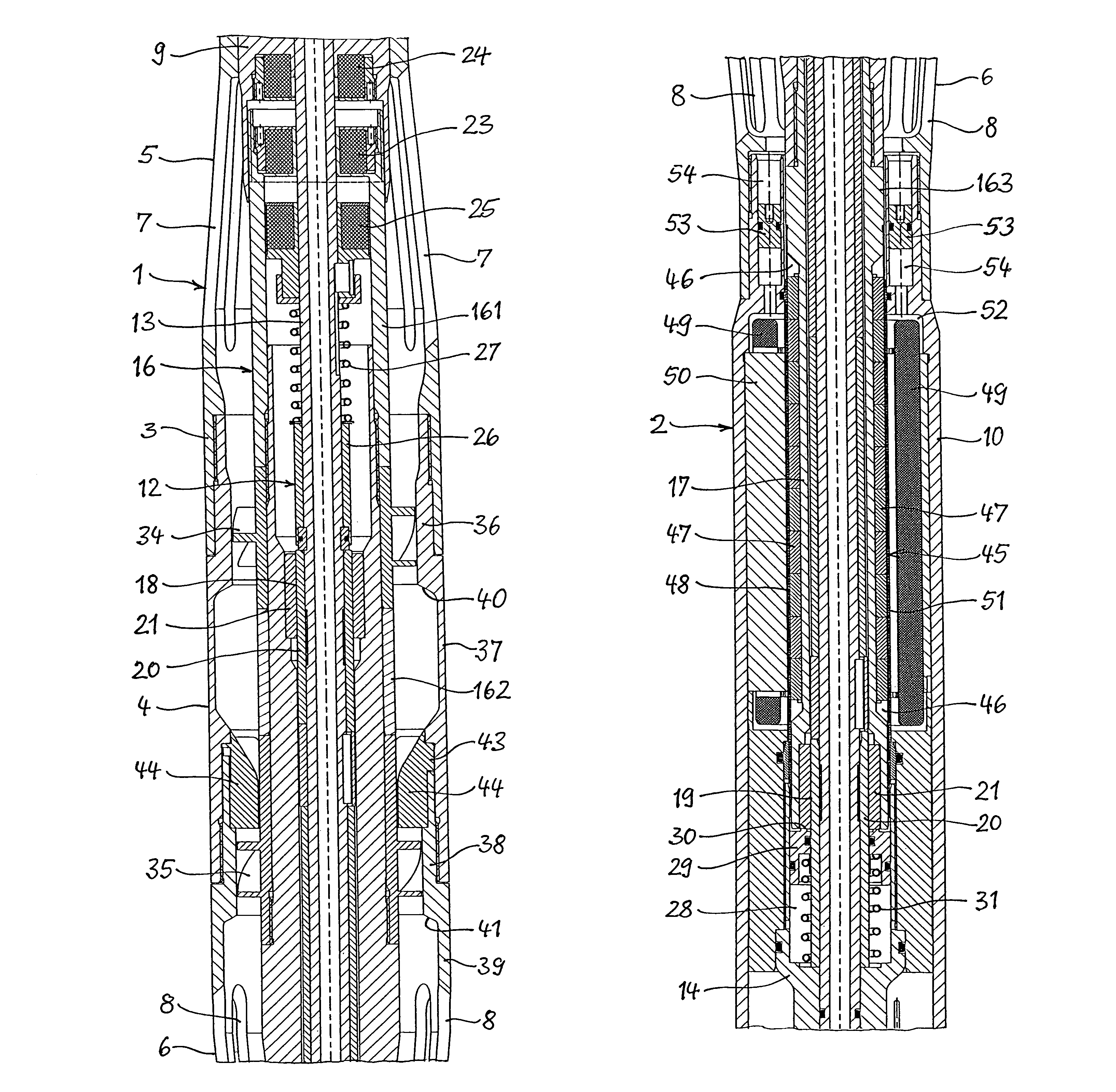
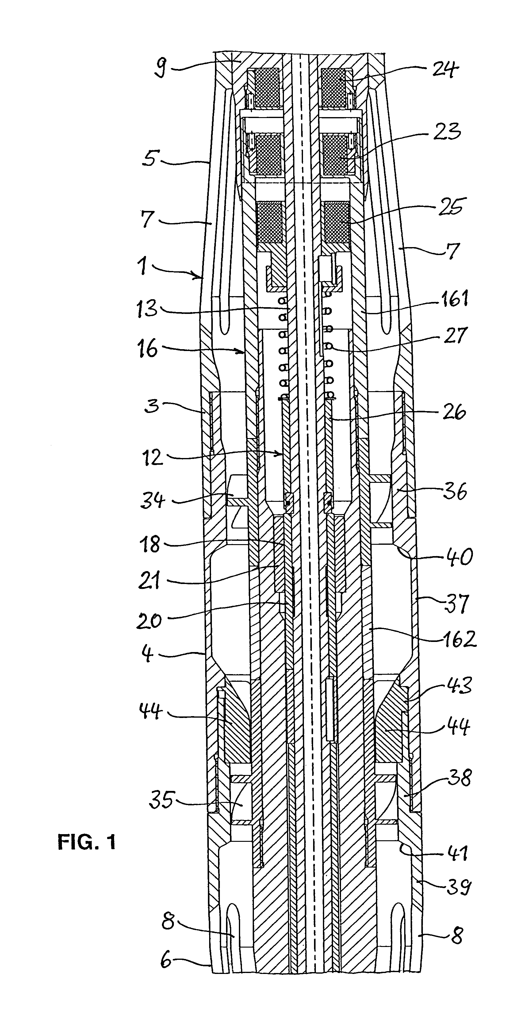
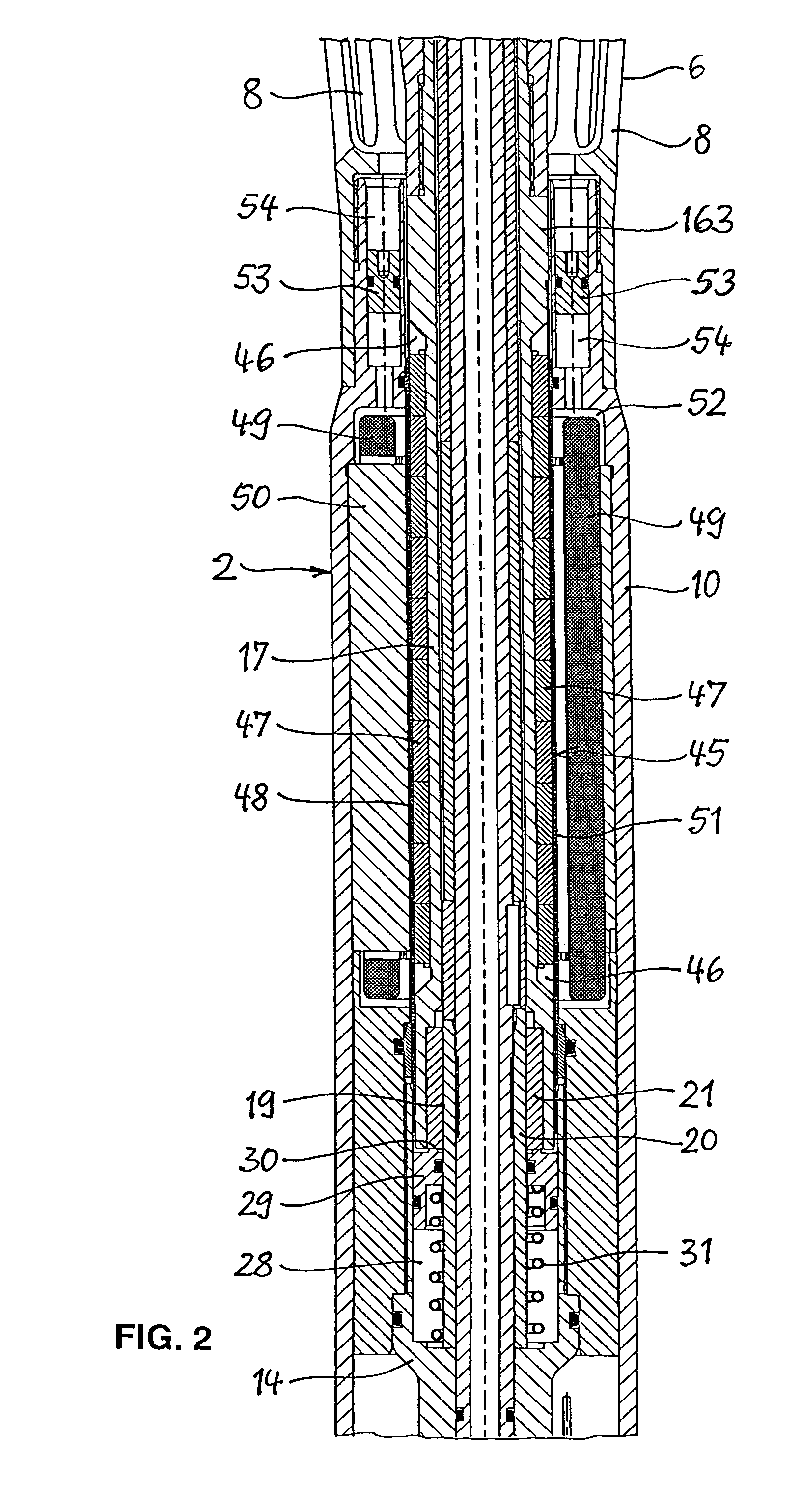
[0018]The turbine 1 illustrated in FIG. 1 and the generator 2 illustrated in FIG. 2 form in combination a constructional unit mountable in a drill string for deep well drilling in order to generate electric power intended to supply measurement instruments and to drive pulsating telemetry devices. The turbine 1 is shown in the drawing in such a way that the afflux end points upwards. The lower end of the turbine 1 is then adjoined by the upper end of the generator 2.

[0019]The turbine 1 has a housing 3 which is composed of three housing sections screwed together. The housing 3 has a cylindrical middle section 4 of an outer diameter which is smaller than the inner diameter of the drill string pipes into which the turbine 1 can be installed according to the intended purpose, with allowance only for the amount of play that is necessary for installation. Adjoining the two ends of the middle section 4 towards the housing ends are conically tapering housing sections 5, 6 which have a plural...


PUM


Abstract

The invention is directed to a turbine with a housing mountable in a drill string and having an inlet opening and an outlet opening for a fluid conveyed through the drill string, and with an impeller arranged in the housing and adapted to be impinged upon by the fluid flowing into the housing, wherein the impeller is axially movably mounted and yieldably supported against the afflux direction in such a way that the supporting force of the yielding support increases as the axial movement of the impeller increases. To reduce the dependence of the turbine rotational frequency and turbine performance on the feed rate and to avoid overloading of the generator, the housing includes in the range of movement of the impeller a frontal first housing section of smaller inner diameter as seen in the afflux direction and a rear second housing section of larger inner diameter as seen in the afflux direction.

Description

CROSS REFERENCE TO RELATED APPLICATIONS[0001]Applicant claims priority under 35 U.S.C. §119 of German Patent Application No. 10 2009 005 330.1 filed Jan. 16, 2009.FIELD OF THE INVENTION[0002]This invention relates to a turbine for driving a generator, with a housing mountable in a drill string and having an inlet opening and an outlet opening for a fluid conveyed through the drill string, with at least one impeller arranged in the housing, which impeller is adapted to be impinged upon by the fluid flowing into the housing, is axially movably mounted and yieldably supported against the afflux direction in such a way that the supporting force of the yielding support increases as the axial movement of the impeller increases.DESCRIPTION OF RELATED ART[0003]In deep well drilling it is common practice to take measurements continuously while drilling by means of measurement systems installed in the drill string and to transmit the measurement results to the surface of the earth by means of...

Claims


Application Information

Patent Timeline
Patent Type & Authority Patents(United States)
IPC IPC(8): F01D17/00
CPCE21B4/02E21B41/0085F03B13/02H02K7/1823
Inventor WINNACKER, HELMUT
Owner WEATHERFORD ENERGY SERVICES
Why Eureka
Try Eureka