Sample and hold time stamp for sensing zero crossing of back electromotive force in 3-phase brushless DC motors

a dc motor and electromotive force technology, applied in the direction of electronic commutators, synchronous motor starters, multiple motor speed/torque control, etc., can solve the problems of processing being interrupted during each commutation, consuming a lot of die space, and using such a dsp

Inactive Publication Date: 2011-10-04
IXYS INTL LTD
View PDF24 Cites 53 Cited by
  • Summary
  • Abstract
  • Description
  • Claims
  • Application Information

AI Technical Summary

Benefits of technology

[0007]A motor control system in a microcontroller determines the position of the rotor of a brushless, direct-current motor by determining the time of zero crossing of back electromotive force (EMF) emanating from each phase winding that is currently not being driven. The time of zero crossing is determined by interpolating voltage differentials that are time stamped. Each voltage differential is the difference between the phase voltage of the non-driven phase winding and the motor neutral point voltage. T

Problems solved by technology

It is undesirable, however, for the processor to be interrupted during each commutation state whil

Method used


Image

  • Sample and hold time stamp for sensing zero crossing of back electromotive force in 3-phase brushless DC motors
  • Sample and hold time stamp for sensing zero crossing of back electromotive force in 3-phase brushless DC motors
  • Sample and hold time stamp for sensing zero crossing of back electromotive force in 3-phase brushless DC motors

Examples


Embodiment Construction

[0021]Reference will now be made in detail to some embodiments of the invention, examples of which are illustrated in the accompanying drawings.

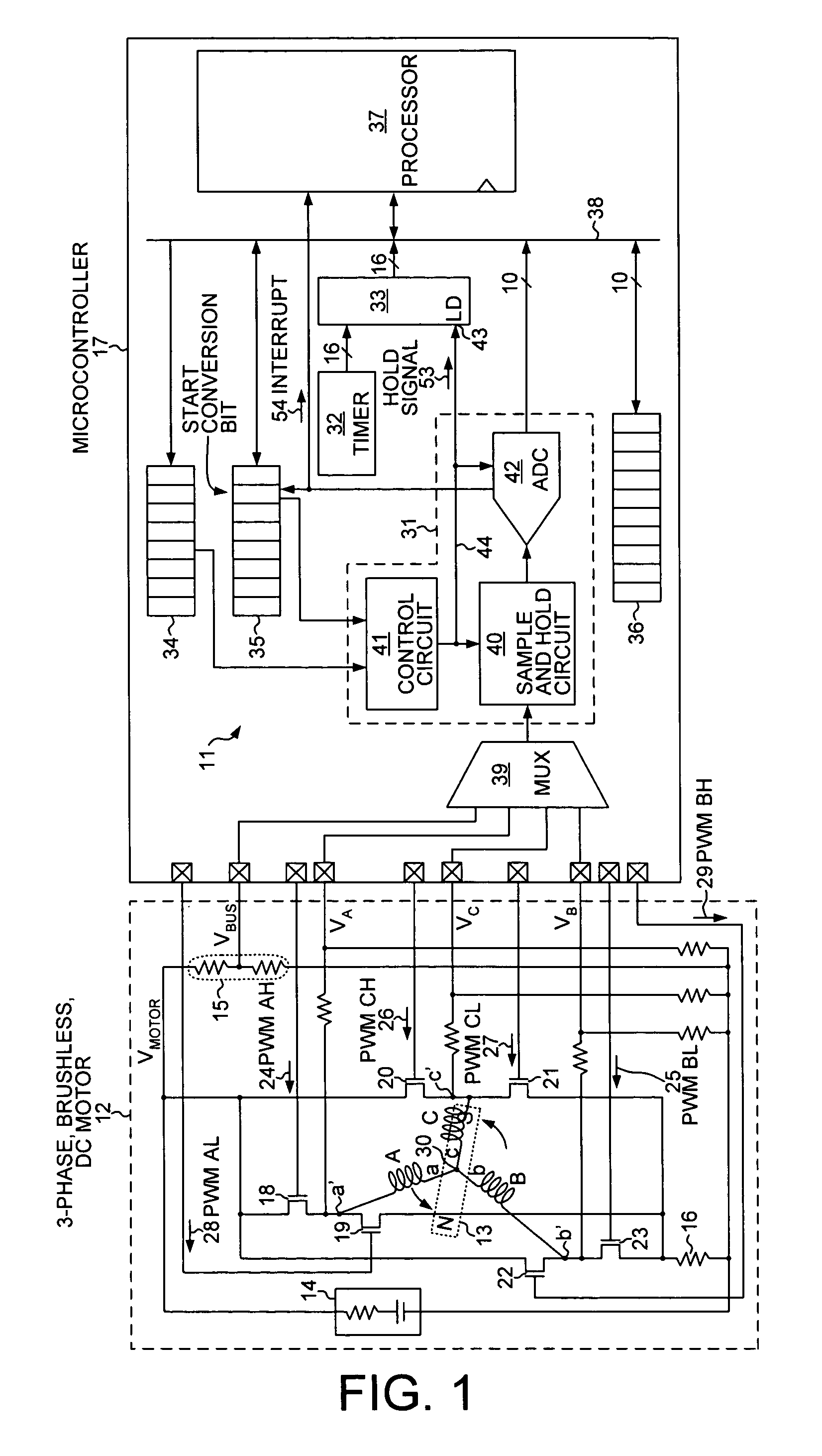
[0022]FIG. 1 shows a motor control system 11 for determining the position of the rotor of a brushless DC motor relative to the stator of the motor. In one embodiment, the motor is a 3-phase, permanent-magnet brushless DC motor 12 that is powered by direct current. Motor 12 has a rotor 13 with two poles and a stator with three phase windings A, B and C. The phase windings are sometimes called induction coils. The three phase windings are separated from one another by 120 degrees. In this embodiment, motor 12 is powered by direct current from battery 14 that is supplied at a voltage (VMOTOR). A voltage divider 15 is used to provide a divided DC supply voltage (VBUS) that approximates the voltage present on a node between the phase windings. A pull-down resistor 16 is used as a current sense resistor to determine the current flowing through thr...


PUM


Abstract

A microcontroller determines the position of the rotor of a brushless, direct-current motor by determining the time of zero crossing of back electromotive force (EMF) emanating from the non-driven phase winding. The zero crossing point is determined by interpolating voltage differentials that are time stamped. Each voltage differential is the difference between the phase voltage of the phase winding and the motor neutral point voltage. The time of zero crossing is determined without using a comparator and without interrupting the processor at each zero crossing point. The processor interpolates the time of zero crossing independently of when the zero crossing point occurs. A hold signal conductor is connected both to a sample and hold circuit and to the load input lead of a time stamp register. The microcontroller simultaneously captures a phase voltage in the sample and hold circuit and a timer count in the time stamp register.

Description

TECHNICAL FIELD[0001]The present invention relates generally to controlling brushless, direct-current electric motors and, more specifically, to a method of determining the position of rotors of such motors.BACKGROUND[0002]An integrated circuit microcontroller can be used to generate the drive currents that power permanent-magnet, brushless DC motors. The drive currents are typically generated from a direct-current (DC) power supply that is switched and alternately inverted. One switching technique used to generate the drive currents uses pulse width modulation (PWM). For example, in an electric motor with three induction coils each separated by 120 degrees, PWM switching signals control the times and the durations at which six switches are opened and closed to produce the six pulsed signals that drive the motor. The process of turning the switches on and off to transfer drive current from one pair of induction coils to the next in a brushless DC motor is called electronic commutati...

Claims


Application Information

Patent Timeline
IPC IPC(8): H02P6/18
CPCH02P6/182
Inventor ALLISON, III, REX L.
Owner IXYS INTL LTD
Why Eureka
Try Eureka