
Inside diameter measuring tool

a measuring tool and inside diameter technology, applied in the direction of mechanical diameter measurement, measurement devices, instruments, etc., can solve the problems of reducing measurement accuracy, deteriorating operability and operation efficiency, and deteriorating the durability of contact pieces and conical parts, so as to reduce frictional force, enhance durability, and work efficiency and operability.

Inactive Publication Date: 2011-10-11
MITUTOYO CORP
View PDF18 Cites 9 Cited by
  • Summary
  • Abstract
  • Description
  • Claims
  • Application Information

AI Technical Summary

Benefits of technology

The present invention provides an inside diameter measurement tool that improves operability, efficiency, and accuracy while minimizing friction between contact pieces and a conical member for enhanced durability. The tool includes a main body, a spindle with a screw, and multiple contact pieces that move in a direction perpendicular to the spindle. A conical member is interposed between the contact pieces and the spindle, which moves the contact pieces in the same direction as the spindle. The lead of the screw is 1.0 mm or more, and the cone angle of the conical member is less than 53 degrees. This design allows for easier measurement of objects, reduces the number of rotations of the spindle, and increases the distance between the contact pieces and the conical surface, reducing friction and improving durability.

Problems solved by technology

However, since the lead of the screw of the spindle of the inside diameter measuring tool is 0.5 mm, when an operator measures objects of various size, he has to undergo a number of rotation of the screw of the spindle in order to advance and retract the contact pieces, resulting in deteriorated operability and operation efficiency.
Consequently, the frictional force caused on the portion on which the contact pieces slide on the conical member increases as compared with the typical arrangement, which is likely to deteriorate the durability of the contact pieces and the conical member.
In other words, the contact pieces is greatly displaced for a relatively small amount of displacement of the spindle, which lowers the measurement accuracy.

Method used


Image

  • Inside diameter measuring tool
  • Inside diameter measuring tool
  • Inside diameter measuring tool

Examples


Embodiment Construction

)

[0019]An exemplary embodiment of the invention will be described below with reference to the attached drawings.

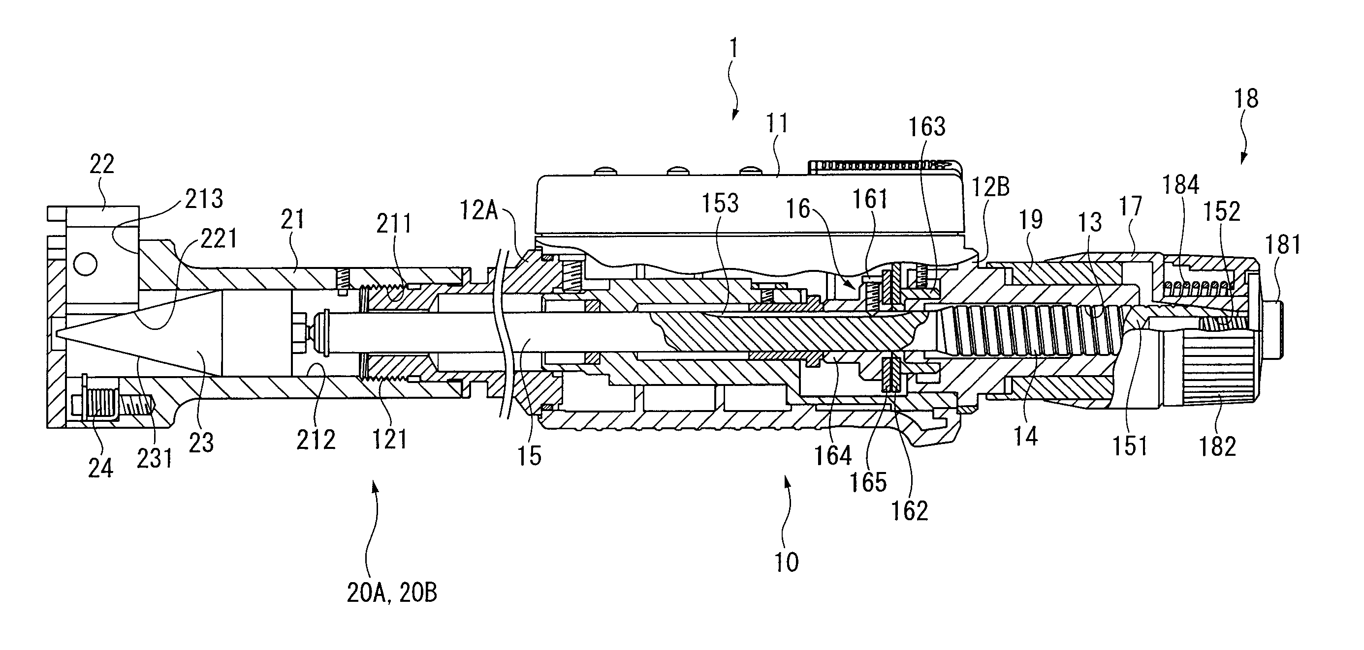
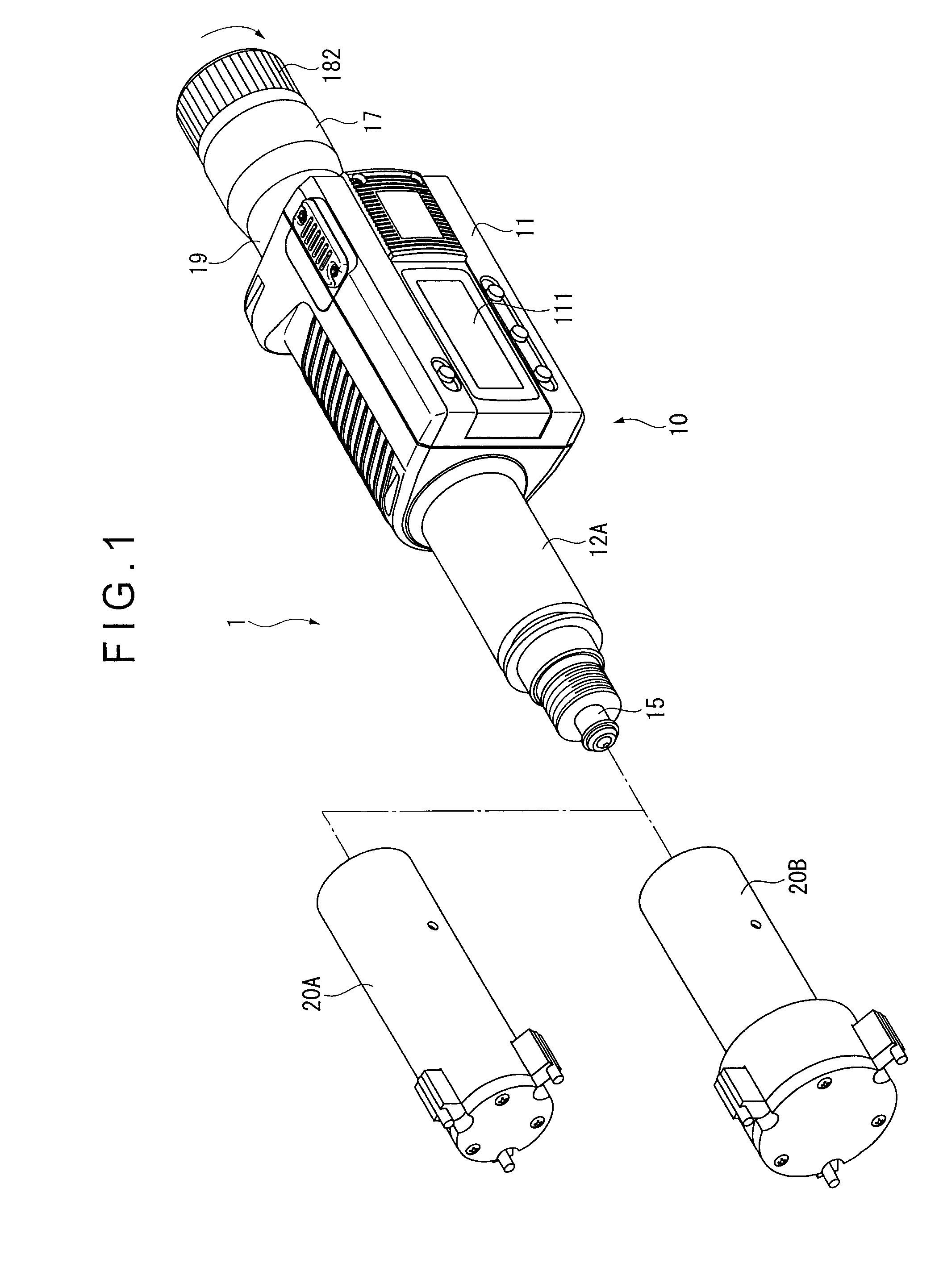
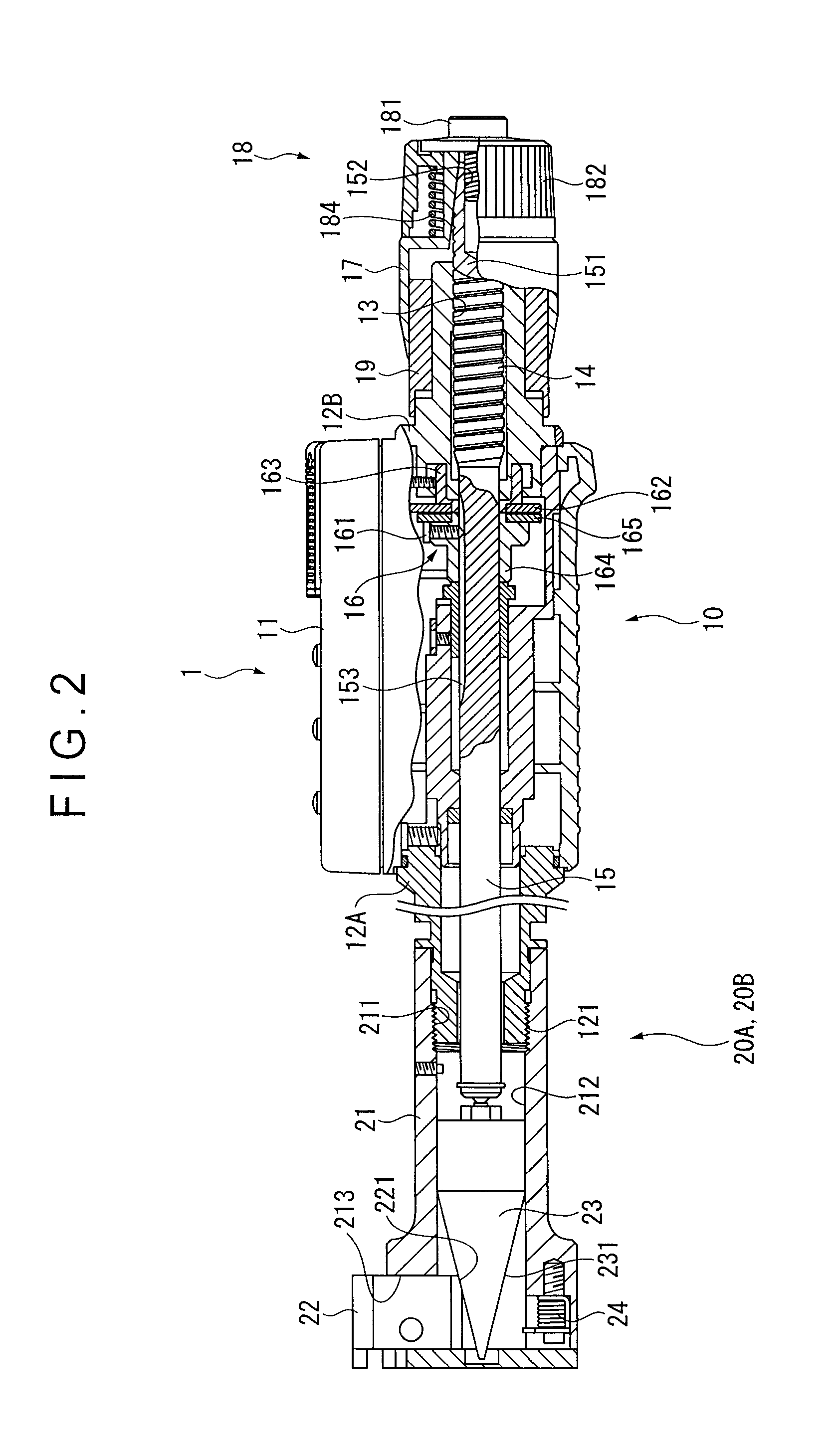
[0020]FIG. 1 is an exploded perspective view of a Holtest 1 (inside diameter measurement tool) according to this exemplary embodiment. FIG. 2 is a cross section of the Holtest 1.

[0021]As shown in FIG. 1, the Holtest 1 includes a main body 10 and a plurality of measuring heads 20A and 20B. The measuring heads 20A and 20B are exchangably used in accordance with an inner diameter of an object to be measured.

Arrangement of Main Body 10

[0022]The main body 10 includes: a rectangular case 11; a substantially cylindrical sleeves 12A, 12B coaxially attached on both sides of the case 11; a spindle 15 screwed with an inner circumference of the sleeve 12B, the spindle 15 advancing and retracting in an axial direction thereof; a detector 16 for detecting the axial displacement of the spindle 15; a thimble 17 for advancing and retracting the spindle 15; and a constant pressure mechanism...


PUM


Abstract

An inside diameter measuring tool includes: a main body; an axially moving spindle having a male screw to be screwed to the main body; a plurality of contact pieces provided on the main body, the measuring pieces moving in a direction substantially orthogonal to the axial direction of the spindle; and a conical member interposed between the contact pieces and the spindle, the conical member advancing and retracting the contact pieces in the direction substantially orthogonal to the axial direction of the spindle. The lead of the male screw of the spindle is 1.0 mm or more and the cone angle of the conical member is less than 53 degrees. Preferably, the lead of the male screw is 2.0 mm and the cone angle of the conical member is approximately 28 degrees.

Description

[0001]The entire disclosure of Japanese Patent Application No. 2008-182569, filed Jul. 14, 2008, is expressly incorporated by reference herein.BACKGROUND OF THE INVENTION[0002]1. Field of the Invention[0003]The present invention relates to an inside diameter measuring tool.[0004]2. Description of Related Art[0005]An inside diameter measuring tool called as a Holtest has been known as a device for measuring an inner diameter of an object to be measured. The inside diameter measuring tool includes: a body; an axially moving spindle having a screw to be screwed to the body; a plurality of contact pieces provided on the body, the contact pieces advancing and retracting in a direction substantially orthogonal to the axial direction of the spindle; and a conical member interposed between the contact pieces and the spindle, the conical member moving the contact pieces in the direction substantially orthogonal to the axial direction of the spindle in accordance with the axial movement of th...

Claims


Application Information

Patent Timeline
Patent Type & Authority Patents(United States)
IPC IPC(8): G01B3/18G01B5/12
CPCG01B5/12G01B3/008
Inventor FUJIKAWA, YUJITACHIKAKE, MASAHIKOMATSUMOTO, KOUJIHAYASHIDA, SHUJI
Owner MITUTOYO CORP
Learn More