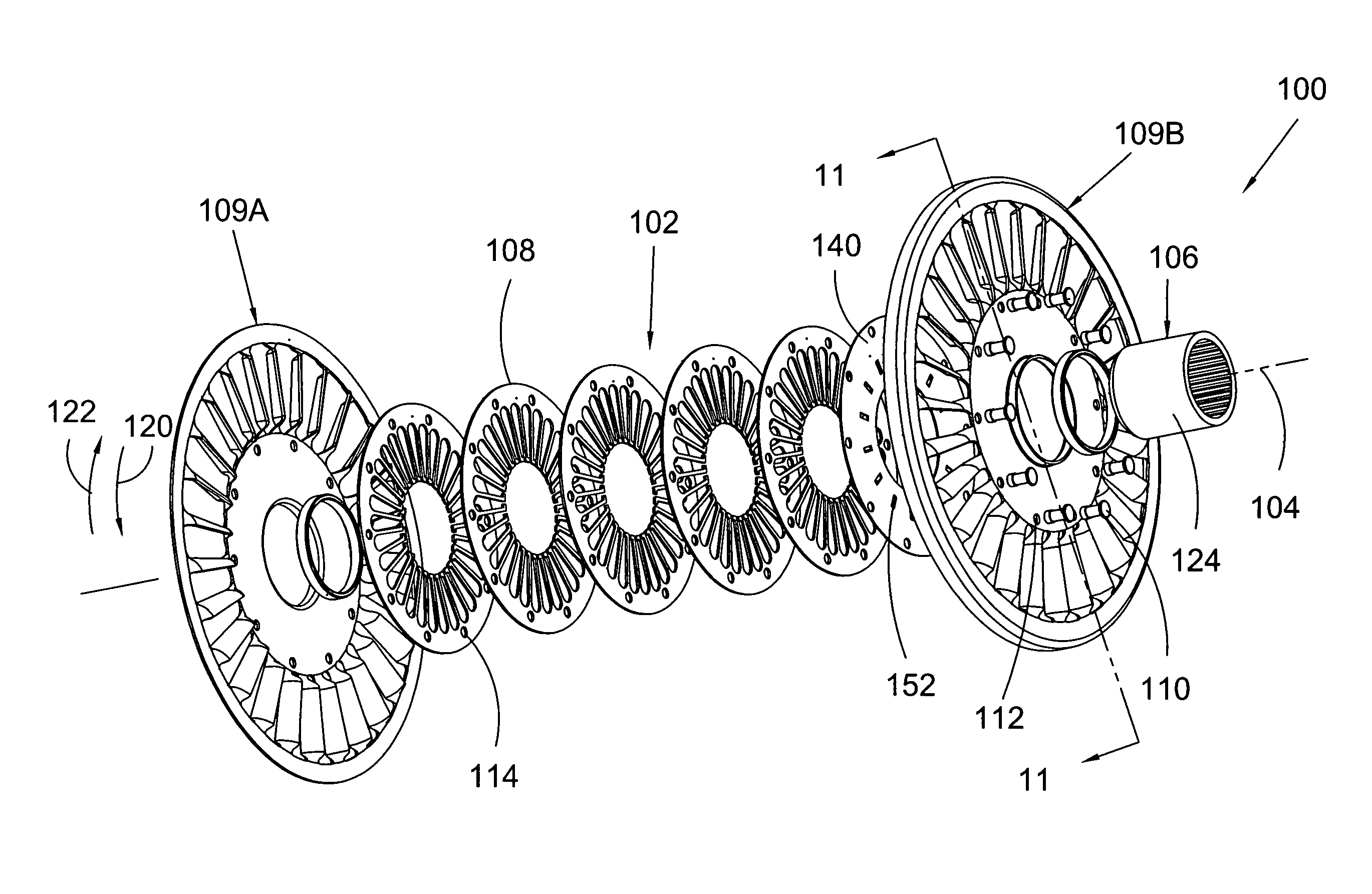
Single component one-way clutch

a one-way clutch and single-component technology, applied in the direction of couplings, belts/chains/gearings, fluid gearings, etc., can solve the problems of high stress, low efficiency of torque converters, and limited peak torque converter efficiency of 92-93%, so as to prevent axial compression and reduce axial width

Inactive Publication Date: 2011-10-11
SCHAEFFLER TECH AG & CO KG
View PDF10 Cites 4 Cited by
  • Summary
  • Abstract
  • Description
  • Claims
  • Application Information

AI Technical Summary

Benefits of technology

[0026]It is a general object of the present invention to provide a one-way clutch having a reduced axial width.
[0027]It is another general object of the present invention to provide a one-way clutch having a means of preventing axial compression.

Problems solved by technology

At speed ratios less than 1, the torque converter is less than 100% efficient.
Peak torque converter efficiency is limited to 92-93% based on losses in the fluid.
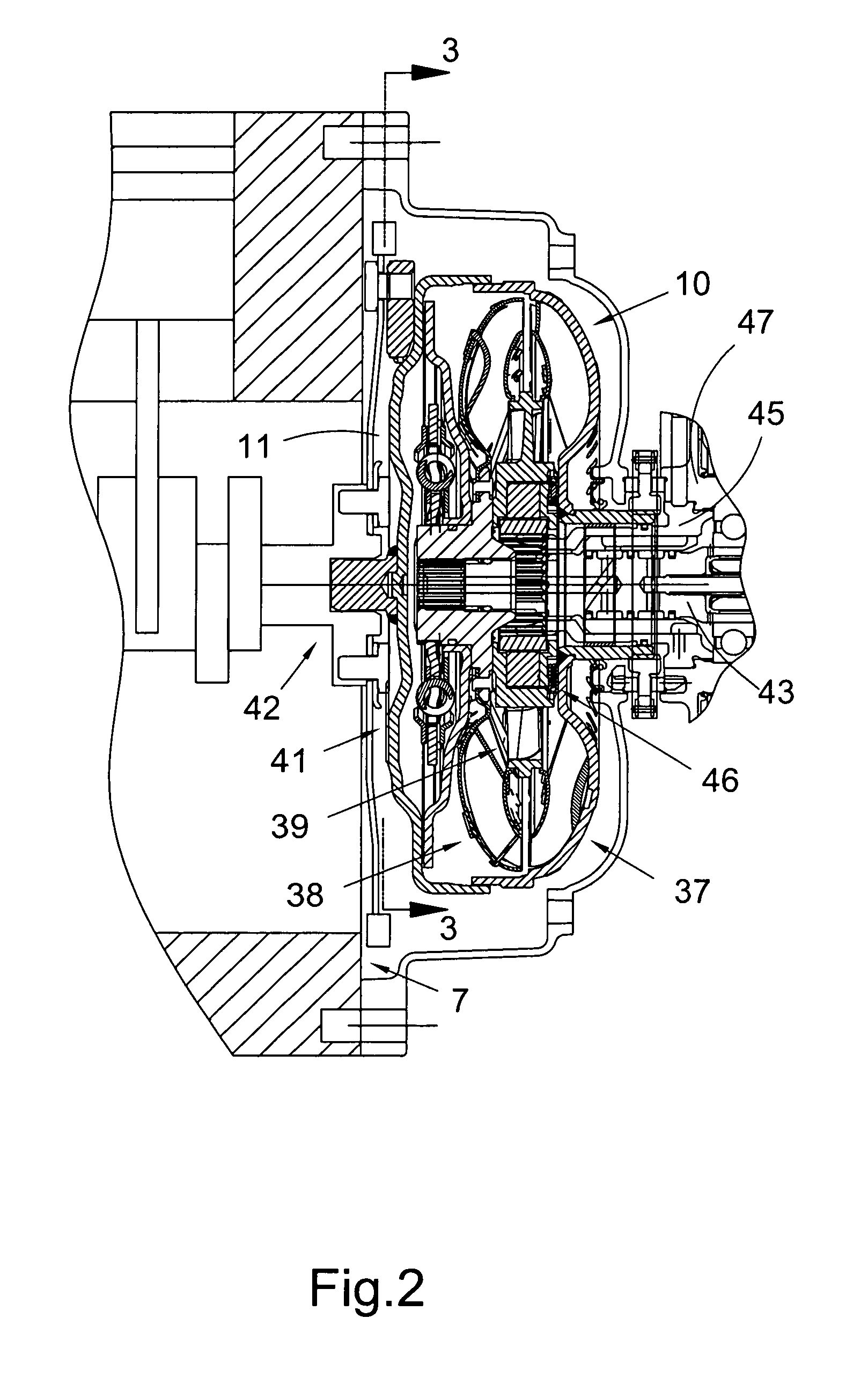
The use of roller clutches, such as clutch 46, also results in high stress due to the limited contact between the rollers in the clutch and the components radially bracketing the rollers.
Therefore, the axial length of a roller clutch must be increased, undesirably increasing the axial space required for a component housing a roller clutch, for example, stator 39.
U.S. Pat. No. 7,040,469 (Shirataki et al.) attempts to address stresses on retainers for roller clutches, but does not address the problem of reducing the axial length of the rollers.
Sprag one-way clutches also suffer a similar undesirable increase in axial length for similar reasons.
U.S. Pat. No. 6,953,112 (Miura) addresses problems associated with asymmetry of a frame for a sprag clutch, but does not address the problem of reducing the axial length of the clutch.
Thus, roller and sprag one-way clutches increases the cost, weight, and complexity of stator 39, and subsequently, of torque converter 10.
Unfortunately, thrust loads associated with a device housing the one-way clutch can cause axial compression of the plates, impairing the function of the clutch.
It is known to increase the size and strength of end plates to withstand the loads, but this approach undesirably increases the width, weight, and cost of the clutch.

Method used


Image

  • Single component one-way clutch
  • Single component one-way clutch
  • Single component one-way clutch

Examples


Embodiment Construction

[0043]At the outset, it should be appreciated that like drawing numbers on different drawing views identify identical, or functionally similar, structural elements of the invention. While the present invention is described with respect to what is presently considered to be the preferred aspects, it is to be understood that the invention as claimed is not limited to the disclosed aspects.

[0044]Furthermore, it is understood that this invention is not limited to the particular methodology, materials and modifications described and as such may, of course, vary. It is also understood that the terminology used herein is for the purpose of describing particular aspects only, and is not intended to limit the scope of the present invention, which is limited only by the appended claims.

[0045]Unless defined otherwise, all technical and scientific terms used herein have the same meaning as commonly understood to one of ordinary skill in the art to which this invention belongs. Although any meth...


PUM


Abstract

A one-way clutch including a race disposed about an axis for the clutch and a wedge plate with a plurality of finger elements extending toward the race and in contact with the race. One of the plate or race is arranged for rotational connection to a torque transmitting element in an automotive device and is arranged to rotate independently of the other of the plate or race for rotation, with respect to the other of the plate or race, in a first rotational direction. The plurality of fingers are arranged to grip the race, to rotationally lock the plate and race, for relative rotation of the plate or race in a second rotational direction, opposite the first rotational direction.

Description

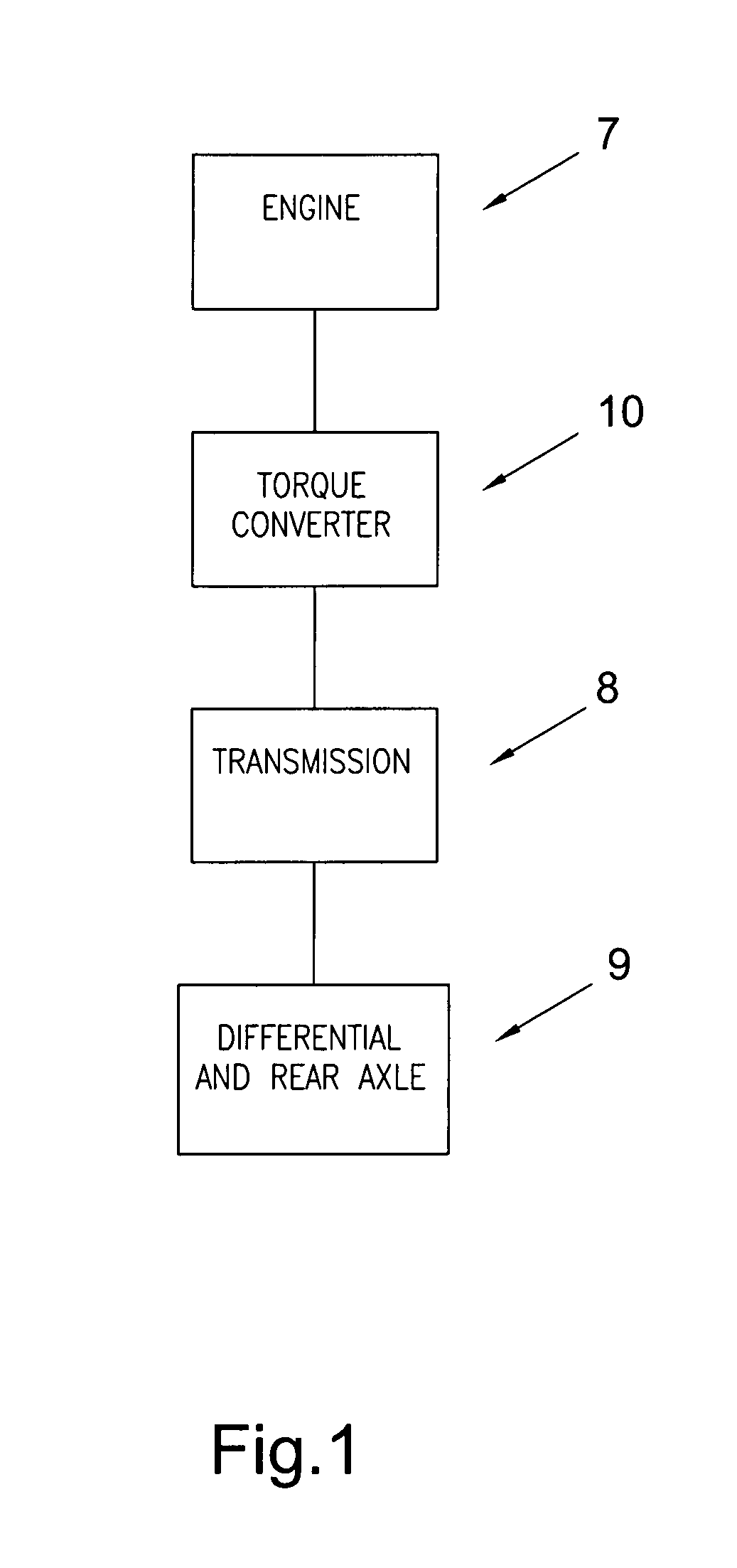
CROSS-REFERENCE TO RELATED APPLICATIONS[0001]This application claims the benefit under 35 U.S.C. §119(e) of U.S. Provisional Application No. 60 / 876,499 filed on Dec. 21, 2006 which application is incorporated herein by reference.FIELD OF THE INVENTION[0002]The invention relates to improvements in apparatus for transmitting force. The force can be between a rotary driving unit (such as the engine of a motor vehicle) and a rotary driven unit (such as the variable-speed transmission in the motor vehicle), or the force can be transmitted within a rotary driving unit (such as the transmission of a motor vehicle). In particular, the invention relates to a one-way clutch with wedges having a circumferential dimension greater than an axial dimension and to a radial one-way clutch with axial spacing.BACKGROUND OF THE INVENTION[0003]FIG. 1 illustrates a general block diagram showing the relationship of the engine 7, torque converter 10, transmission 8, and differential / axle assembly 9 in a ty...

Claims


Application Information

Patent Timeline
Patent Type & Authority Patents(United States)
IPC IPC(8): F16D41/069F16H41/24
CPCF16D41/069F16H41/24F16H2041/246
Inventor DAVIS, MICHAEL
Owner SCHAEFFLER TECH AG & CO KG
Why Eureka
Try Eureka