Opening/closing device for vehicle door

a technology for opening/closing devices and vehicles, which is applied in the direction of locks, doors, carpet fasteners, etc., can solve problems such as blocking the power transmission between, and achieve the effect of reducing the space for installing the canceling lever

Inactive Publication Date: 2011-10-11
AISIN SEIKI KK
View PDF17 Cites 16 Cited by
  • Summary
  • Abstract
  • Description
  • Claims
  • Application Information

AI Technical Summary

Benefits of technology

[0007]Accordingly, it is an objective of the present invention to provide a vehicle door opening / closing device that performs both of a closer operation and a releasing operation using a single drive unit and ensures canceling operation without hampering the releasing operation even in a panic state.
[0011]In this configuration, since the canceling lever of the canceling mechanism is arranged coaxially with the releasing lever used in the releasing operation, the space for installing the canceling lever is reduced. Also, by causing the pressing portion to press the releasing lever so as to pivot the releasing lever when the canceling operation is performed, the canceling lever switches the latch mechanism from, for example, the fully latched state or the half-latched state to the unlatched state. Further, since the canceling lever is permitted to pivot relative to the releasing lever, the canceling lever permits the releasing lever to pivot independently without following the releasing lever, and thus does not hamper the releasing operation.
[0013]In this configuration, the pressing portion of the canceling lever cannot be engaged with the locking mechanism when the vehicle door is in the locked state. This prevents transmission of the manipulation force of the door handle to the pressing portion through the locking mechanism. The canceling lever thus does not pivot. Accordingly, if the door handle is manipulated, for example, when the vehicle door is being switched from the locked state to the unlocked state through activation of the drive source used in switching of the locking mechanism, the power transmission between the drive source and the drive lever is prevented from being blocked by the above-described operation of the canceling lever. The releasing operation is thus carried out continuously regardless of manipulation of the door handle.
[0019]Preferably, the canceling lever of the canceling mechanism is arranged coaxially with the releasing lever used in the releasing operation. This reduces the space for installing the canceling lever. Further, by pressing the releasing lever by means of the pressing portion to pivot the releasing lever when the canceling operation is performed, the canceling lever switches the latch mechanism from, for example, the fully latched state or the half-latched state to the unlatched state. Further, since the canceling lever is permitted to pivot relative to the releasing lever, the canceling lever allows the releasing lever to pivot independently without following the releasing lever. The canceling lever thus does not hamper the releasing operation.

Problems solved by technology

Further, when the vehicle door is held in the unlocked state by the locking mechanism, the manipulation force of the door handle is transmitted to the canceling mechanism through the locking mechanism, thus blocking the power transmission between the drive source and the drive lever (canceling operation).

Method used


Image

  • Opening/closing device for vehicle door
  • Opening/closing device for vehicle door
  • Opening/closing device for vehicle door

Examples


Embodiment Construction

[0035]An embodiment of the present invention will now be described with reference to the attached drawings.

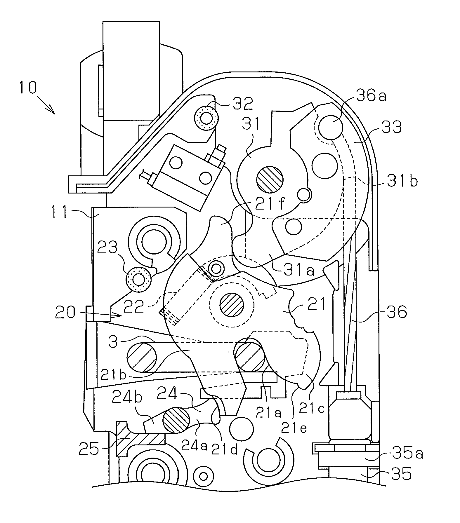
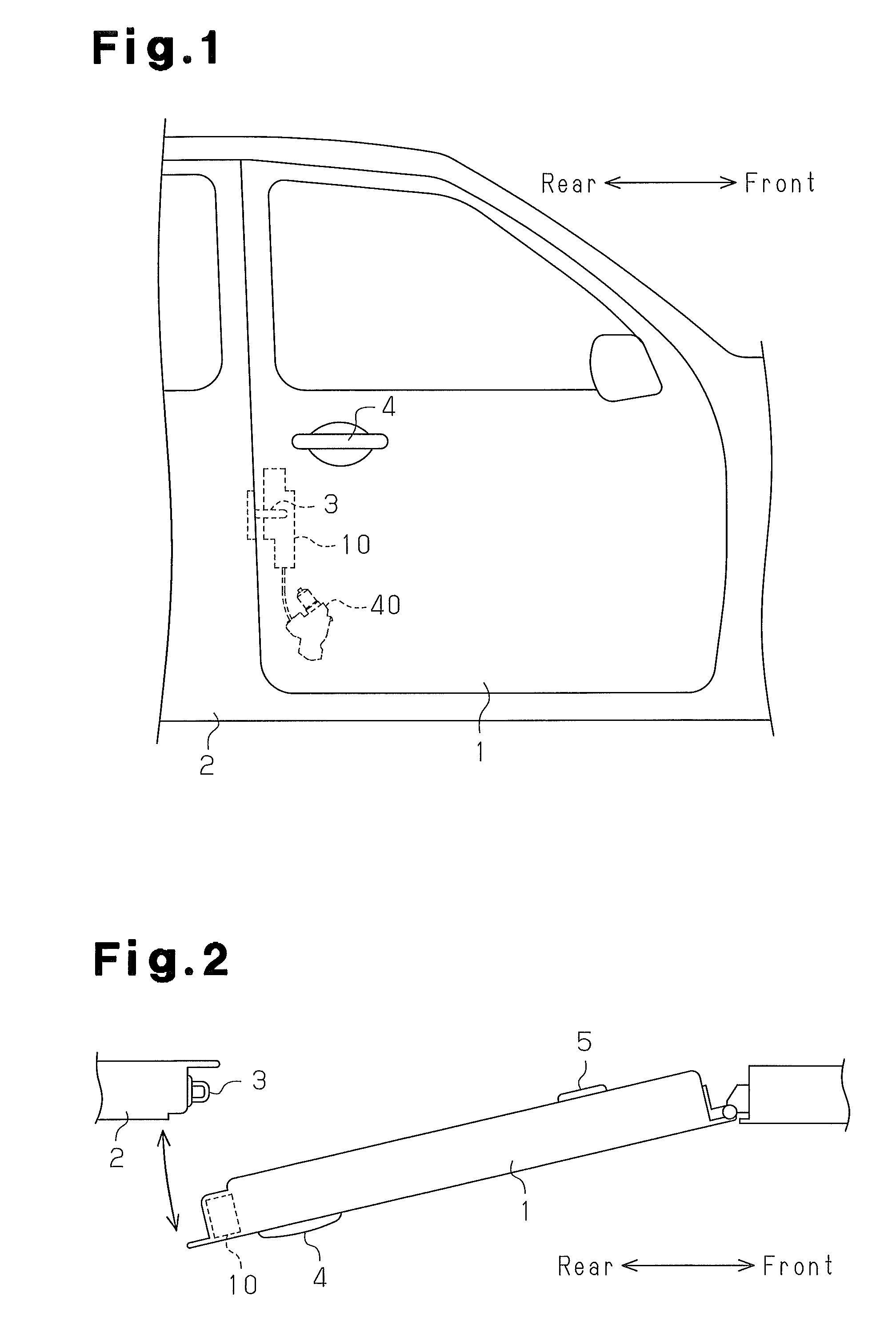
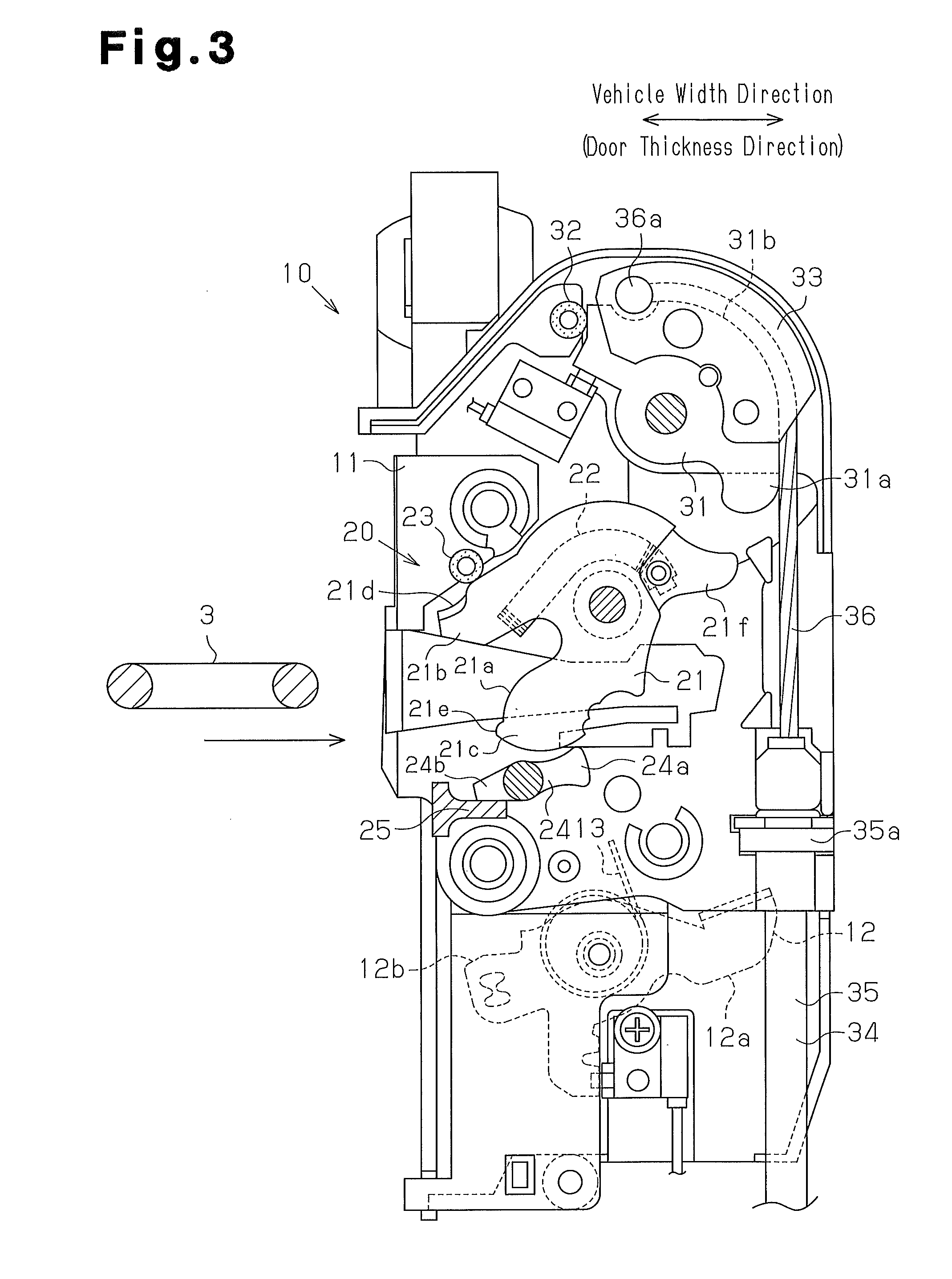
[0036]FIG. 1 is a front view showing a vehicle door 1 according to one embodiment of the present invention, and FIG. 2 is a plan view showing the vehicle door 1 illustrated in FIG. 1. As shown in FIGS. 1 and 2, the vehicle door 1 is a swing door that is hinged to a body frame 2 in such a manner as to selectively open and close an opening of the passenger compartment of the vehicle. A door latch device 10 is mounted in a rear end portion of the vehicle door 1. The door latch device 10 is engaged with a substantially U-shaped striker 3 fixed to the body frame 2 and maintains the vehicle door 1 ajar or fully closed. The door latch device 10 is connected to an outside door handle 4 mounted in an outer wall of the vehicle door 1 and an inside door handle 5 arranged in an inner wall of the vehicle door 1. When manipulation force acting on either one of the door handles 4, 5 is transm...


PUM


Abstract

A vehicle door opening / closing device having a latch mechanism, a locking mechanism, an actuator, and a canceling mechanism is provided. The actuator has an electric motor and a pivotable drive lever. The canceling mechanism operates to block transmission of power between the electric motor and the drive lever when manipulation force of a vehicle door handle is transmitted to the canceling mechanism through the locking mechanism. The manipulation force of the door handle is transmitted to the canceling mechanism only when the vehicle door is in an unlocked state.

Description

FIELD OF THE INVENTION[0001]The present invention relates to a vehicle door opening / closing device.BACKGROUND OF THE INVENTION[0002]As a conventional vehicle door opening / closing device, a device described in Patent Document 1, for example, has been known. In the door opening / closing device of Patent Document 1, when the drive force produced by a drive unit is transmitted to a latch mechanism, the latch mechanism is switched from a half-latched state to a fully latched state so as to operate the vehicle door to close (closer operation). Specifically, by activating an electric motor in such a manner as to pivot a drive lever in one direction, a drive wire is pulled so as to transmit the drive force of the drive unit to the latch mechanism.[0003]Also, in the door opening / closing device described in Patent Document 1, when the closer operation is performed and manipulation force of a door handle is transmitted to an open lever, the open lever is pivoted through a cancel cable connected...

Claims


Application Information

Patent Timeline
Patent Type & Authority Patents(United States)
IPC IPC(8): E05C3/16E05C3/06B60J5/00E05B85/24E05B77/32E05B79/08E05B81/20E05B81/38
CPCE05B81/20E05B53/008Y10S292/23Y10T292/1047Y10T292/1082E05B81/38
Inventor AKIZUKI, RYUJIROSHIMIZU, KIMITONISHIO, TAKASHI
Owner AISIN SEIKI KK
Why Eureka
Try Eureka