Wireless lighting devices and applications

a technology of lighting devices and wireless control, applied in the direction of lighting support devices, ways, with built-in power, etc., can solve the problems of not being optimal for many applications, and achieve the effects of reducing energy consumption, reducing energy consumption, and facilitating installation

Inactive Publication Date: 2011-10-11
RING LLC
View PDF42 Cites 293 Cited by
  • Summary
  • Abstract
  • Description
  • Claims
  • Application Information

AI Technical Summary

Benefits of technology

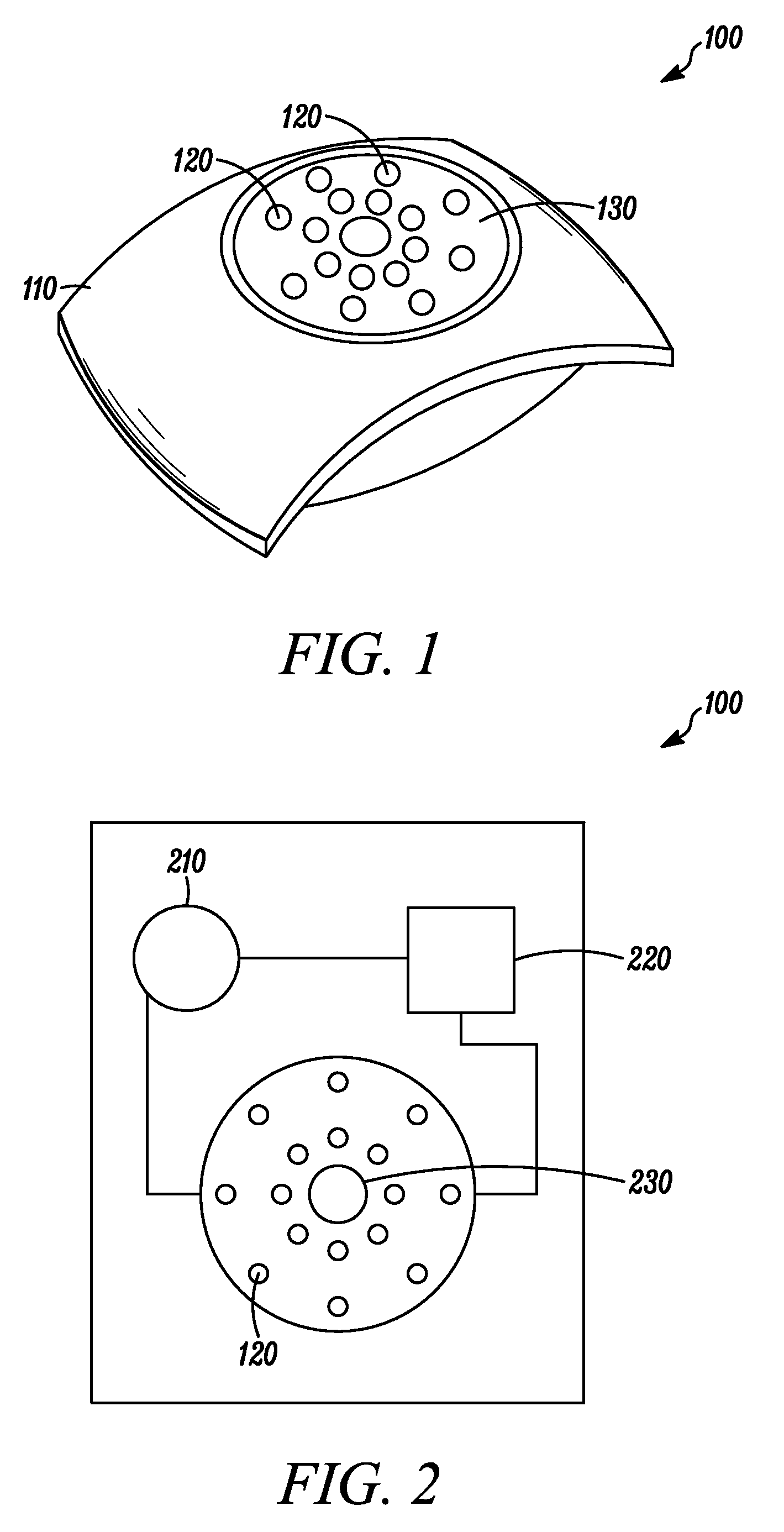
[0007]The present invention is directed generally to devices and applications related to the use of wireless control and wireless power in light emitting diode (LED) based lighting devices. More particularly, the devices and applications according to various embodiments of the present invention make use of wireless control and wireless power in lighting devices to provide advantages in ease of installation, in the ability to install lighting in locations independent of a connection to wired power, in cost savings, in energy efficiency and in the reduction of energy consumption at times of peak demand through controls and power management and in safety, security, and convenience for the end user.
[0008]Wireless control, as in relation to lighting facilities of the present invention, may be defined as any control aspect that provides a controlling function to the lighting facility without the use of a wired connection, such as a wired control interface, wired power control, and the like. Control aspects may include, but are not limited to, a wireless remote control interface (e.g. RF remote control), a wireless power controller (e.g. control of the source of power to the LEDs, such as including integrated energy storage device(s) and AC power), a wireless control input (e.g. an environmental sensor input), internal programmed control (e.g. internal program store controlled through a state machine or processor), and the like. In embodiments, cost savings and power management may be implemented through wireless control. In embodiments, wireless control may enable a distributed intelligence architecture where the LED lighting facility may operate in an autonomous manner in response to its wireless control inputs or internal program. In embodiment, wireless control may be used in conjunction with wireless power to allow operation of the lighting facility completely independent of the power grid.
[0009]In some embodiments, wireless control allows the installation of the device in any indoor or outdoor location where light may be desired without the need for a wired connection to control it. In some embodiments, wireless control is used in a lighting device with a wired connection but allows an alternate method of control of the light rather than by its wired connection. In some embodiments, a lighting circuit may have multiple lights on the circuit, but wireless control built into the lights on that lighting circuit may allow them to be independently controlled.
[0011]In some embodiments, a wireless power source integrated into the lighting device allows the installation of the lighting device in any indoor or outdoor location where light may be desired without the need for a wired connection to an AC power source. In other embodiments there is a wired connection to an AC power source, but the wireless power source is used when advantageous, for example as a backup power source in an emergency or as an alternative power source to provide energy efficiency or cost savings.
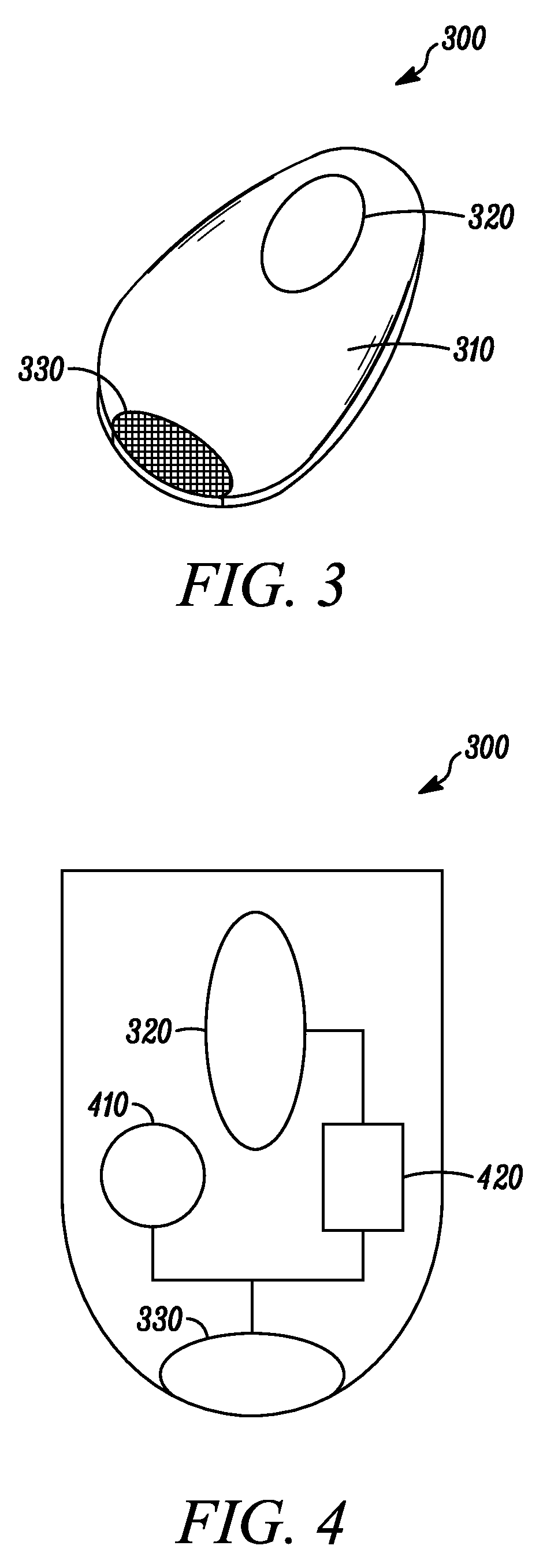
[0018]One advantage of the present invention is the ability to build intelligent lighting systems where wireless control and wireless power along with the ability to take advantage of the additional functionality is built into the light itself. One advantage of the present invention is the ability to provide battery back-up power within an LED bulb or tube that can fit into conventional AC powered sockets. In some embodiments, these lights are able to provide light in the event of power outage, and in other embodiments these lights may be used to reduce demand on the power grid by switching to battery power at peak times, then recharging off peak. One advantage of the present invention is the ability to create programmable light bulbs, tubes or lamps with integrated sensors. These intelligent lights may contain integrated controls that turn on, off, or change light intensity based on a programmable schedule, the detection of sensor inputs, or a change in lighting conditions. One advantage of the present invention is the ability to communicate controls to and between these LED lighting facilities. In some embodiments, intelligent lights may contain wireless transmitters and receivers allowing them to coordinate functions within groups of light bulbs or allowing them to receive control and programming over a network as well as forward or route traffic to other light bulbs that are part of the network. Thus, for example, a removable light bulb may also act as a node in a network of light bulbs providing the ability to deploy a lighting installation and a network to control the lighting installation by plugging light bulbs into sockets.

Problems solved by technology

While LED lighting is becoming an attractive option for certain applications, it is not optimal for many applications.

Method used


Image

  • Wireless lighting devices and applications
  • Wireless lighting devices and applications
  • Wireless lighting devices and applications

Examples


Embodiment Construction

[0091]The claimed subject matter is described with reference to the drawings, wherein like reference numerals are used to refer to like elements throughout. In the following description, for purposes of explanation, numerous specific details are set forth in order to provide a thorough understanding of the subject innovation. It may be evident, however, that the claimed subject matter may be practiced without these specific details. In other instances, well-known structures and devices are shown in block diagram form in order to facilitate describing the subject innovation. Moreover, it is to be appreciated that the drawings may not be to scale.

[0092]As utilized herein, terms “component,”“system,” and the like are intended to refer to a computer-related entity, either hardware, software (e.g., in execution), and / or firmware. For example, a component can be a process running on a processor, a processor, an object, an executable, a program, and / or a computer. By way of illustration, b...


PUM


Abstract

In embodiments of the present invention improved capabilities are described for systems and methods that employ a control component and / or power source integrated in an LED based light source to control and / or power the LED light source wirelessly. In embodiments, the LED based light source may take the form of a standard light bulb that plugs into a standard lighting socket or fixture.

Description

CROSS-REFERENCE TO RELATED APPLICATIONS[0001]This application claims the benefit of the following U.S. patent applications, each of which is hereby incorporated by reference in its entirety: U.S. Appl. No. 61 / 118,245 filed Nov. 26, 2008; U.S. Appl. No. 61 / 150,477 filed Feb. 6, 2009; U.S. Appl. No. 61 / 167,556 filed Apr. 8, 2009; U.S. Appl. No. 61 / 186,097 filed Jun. 11, 2009; U.S. Appl. No. 61 / 234,024 filed Aug. 14, 2009; U.S. Appl. No. 61 / 246,362 filed Sep. 28, 2009; U.S. Appl. No. 61 / 118,257 filed Nov. 26, 2008; and U.S. Appl. No. 61 / 167,655 filed Apr. 8, 2009.[0002]This application is a continuation-in-part of the pending U.S. application Ser. No. 11 / 847,509 filed Aug. 30, 2007. This application is a continuation-in-part of the pending U.S. application Ser. No. 11 / 692,075 filed Mar. 27, 2007, and application Ser. No. 11 / 692,075 claims the benefit of U.S. Appl. No. 60 / 786,636 filed Mar. 28, 2006.BACKGROUND[0003]1. Field[0004]The present invention is directed generally to devices and...

Claims


Application Information

Patent Timeline
Patent Type & Authority Patents(United States)
IPC IPC(8): F21S4/00H05B44/00
CPCH05B33/0803H05B37/0272H05B37/03H05B33/0854Y02B20/383F21S9/022F21V23/0442F21W2111/027F21Y2101/02Y10S362/806F21Y2115/10F21Y2115/15H05B45/10Y02B20/30H05B47/115H05B47/28H05B47/195H05B47/24H05B45/357Y02B20/40
Inventor RECKER, MICHAEL V.LEVINE, DAVID B.
Owner RING LLC
Why Eureka
Try Eureka