

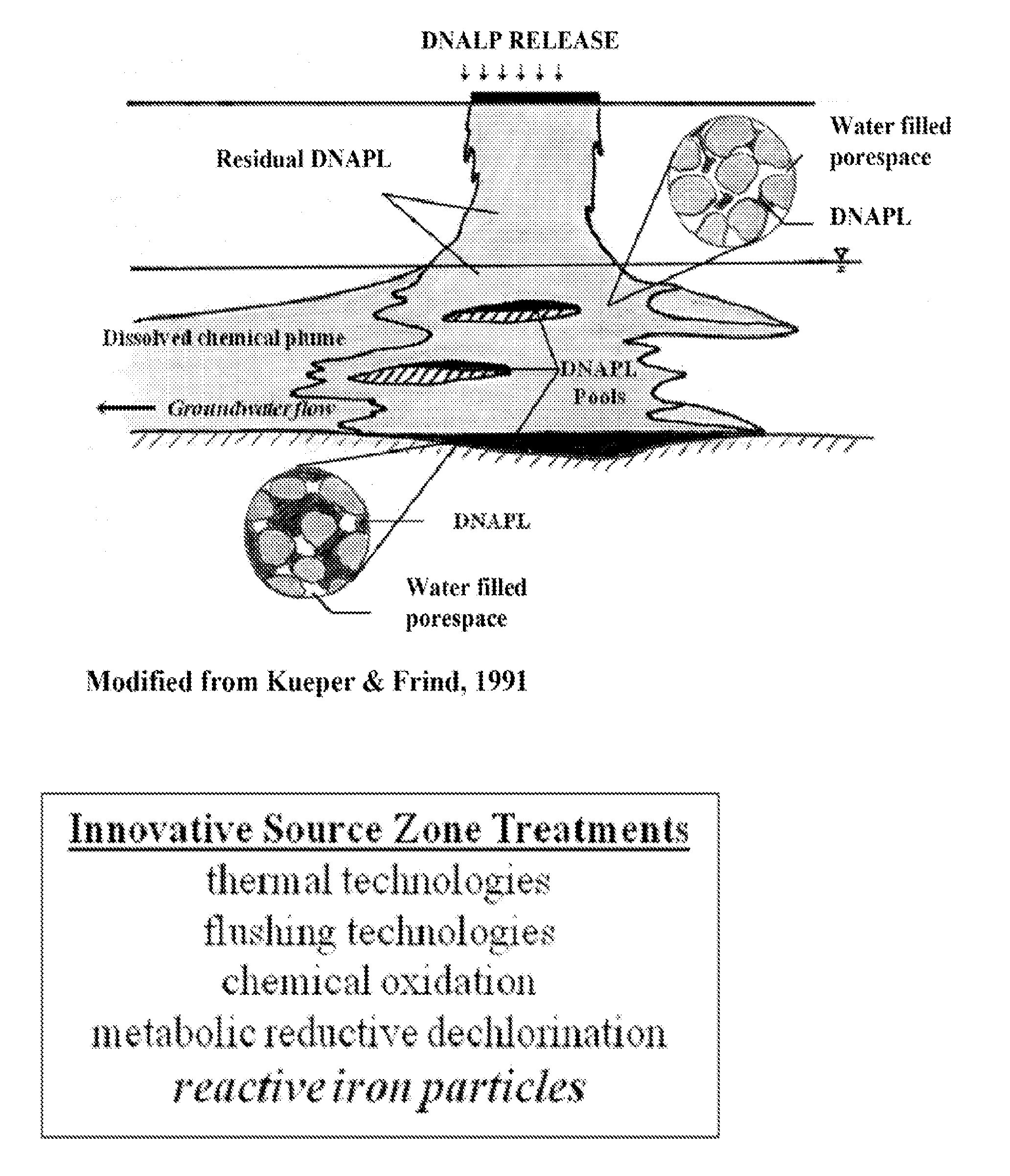
Iron-mediated remediation within nonaquous phase liquid
- Summary
- Abstract
- Description
- Claims
- Application Information
AI Technical Summary
Benefits of technology
Problems solved by technology
Method used
Image

Examples
example 1
[0045]The results described herein show that ZVI mediated reduction of trichloroethylene (TCE) to ethene / ethane within a NAPL is most efficient in the presence of water. The utility of iron-mediated TCE-DNAPL reduction was evaluated with emphasis placed on understanding the influence water content has on the TCE reduction process within a NAPL.
[0046]Experiments were conducted in 125-mL serum bottles containing approximately 1.0 to 2.5 g of commercially available iron (Reactive Nanoscale Iron Particles (RNIP) or MTI iron) or iron particles created using a borohydride reduction pathway (e.g., Glavee et al. 1995). Table 1 shows NAPL compositions for reactivity assessment. Fluids placed in the serum bottles comprised 50 g of a TCE, butanol, and water mixture in an argon atmosphere (head space volume is approximately 70 mL). The TCE mixture was designed to ensure initial TCE concentration was constant in all experiments (approximately 230 g / L), while initial water contents (ranging from ...
PUM
 Abstract
Description
Claims
Application Information