Rapid delivery and/or withdrawal of fluids

a fluid delivery and fluid technology, applied in the field of fluid delivery and/or fluid withdrawal, can solve the problems of complex procedures, inability to perform non-medical settings, and require sophisticated training of practitioners, and achieve the effects of high acceleration, high energy, and speed of operation

Inactive Publication Date: 2018-11-01
YOURBIO HEALTH INC
View PDF2 Cites 8 Cited by
  • Summary
  • Abstract
  • Description
  • Claims
  • Application Information

AI Technical Summary

Benefits of technology

[0005]In one aspect, the present invention is generally directed to a simple, one-piece, low-profile, high acceleration, high energy, actuation mechanism for inserting microneedles (or other objects) into the skin for the purpose of delivering or withdrawing bodily fluids, such as blood or interstitial fluid.
[0006]In one set of embodiments, a device of the invention is actuated by a reversibly deformable structure which can provide advantage in ease of operation, speed of operation, reduction or elimination of pain, etc.
[0029]Another aspect of the invention involves a device able to withdraw a substance or deliver a substance from or to a subject including a triggering mechanism able to move a substance transfer component, relative to the skin of a subject, in a short period of time, and / or at a relatively high velocity, and / or at a relatively high force, and / or at a relatively high pressure.

Problems solved by technology

However, such procedures are complicated and require sophisticated training of practitioners, and often cannot be done in non-medical settings.

Method used


Image

  • Rapid delivery and/or withdrawal of fluids
  • Rapid delivery and/or withdrawal of fluids
  • Rapid delivery and/or withdrawal of fluids

Examples


example 1

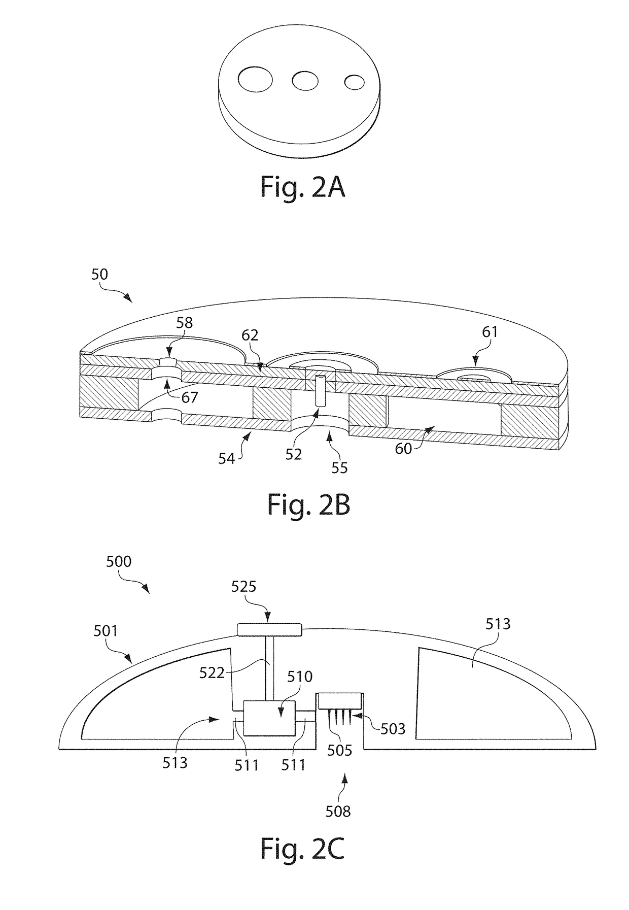
[0253]This example illustrates a device for inserting a microneedle array into the skin of a subject. FIG. 13A shows a device 800 including a fluid transporter (e.g., microneedle array 833), a reversibly deformable structure (e.g., snap dome 832), an activator (e.g., activation button 831), a retraction mechanism (e.g., silicone foam 835), and structural components constructed from multiple layers of polycarbonate bonded together using a double-sided adhesive, such as 3M 1509 or 3M 1513 tape. The microneedle arrays can be bonded to laminated post 837 on the underside of a snap dome. Structural components 838, as well as post 837, are formed from polycarbonate and 3M 1509 or 3M 1513 adhesive. The arrays may range in needle number (4 to 28 needles), needle length (350 to 1000 micrometers), and / or arrangement (square, rectangular, and circular arrays), with array footprints of less than 3 mm in diameter, where the “footprint” is the area of the base to which the needles are attached.

[0...

example 2

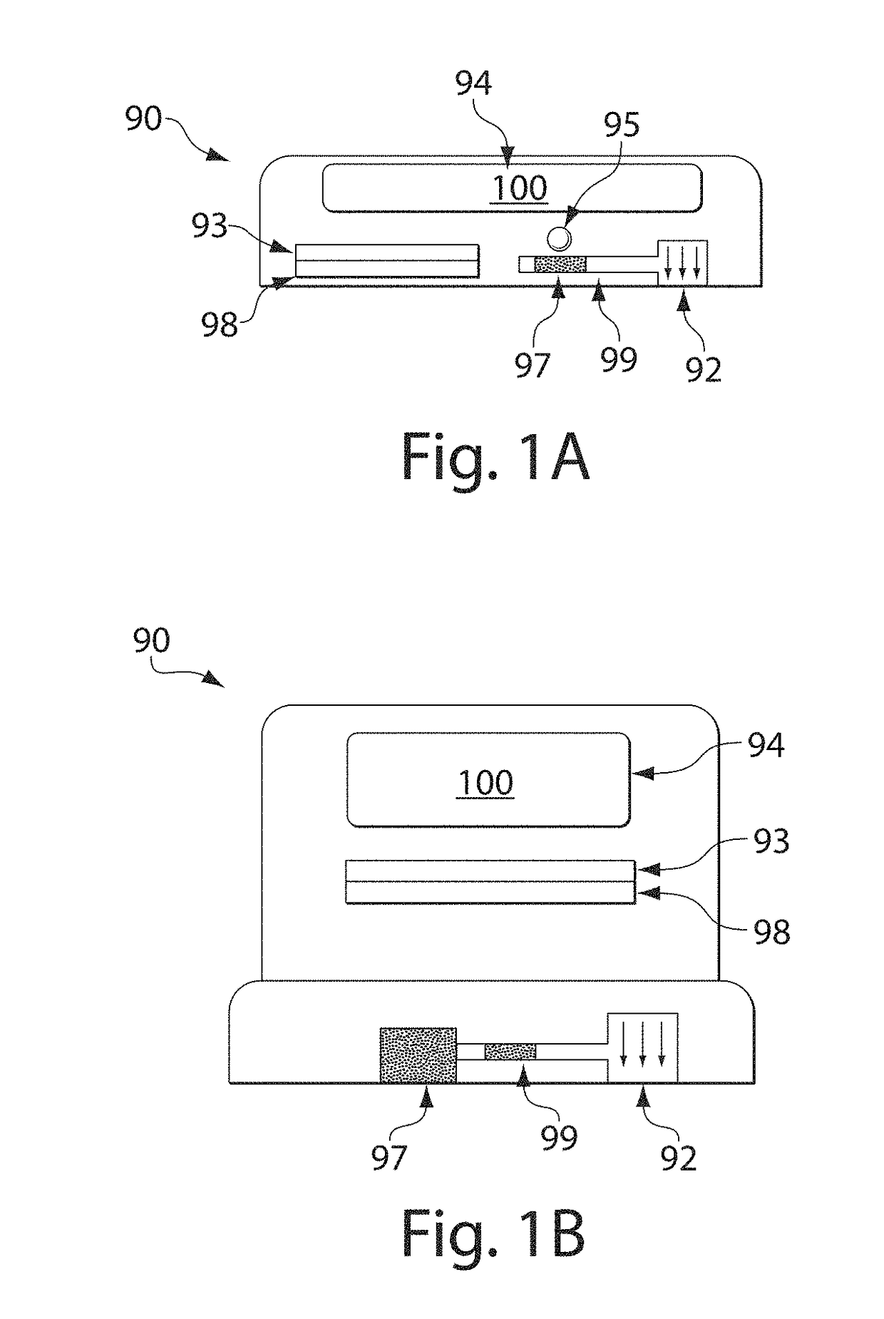
[0255]This example illustrates a device for withdrawing blood using vacuum. This device is shown in FIG. 13B. This device includes a vacuum chamber comprising layers of polycarbonate, polyethylene terephthalate glycol (PETG), and silicone bonded together using a double-sided adhesive, such as 3M 1509 or 3M 1513 tape. The chamber is approximately 2.7 cm in diameter and 0.6 cm high, with cup opening 858 in the base that ranges from 3 to 7 mm in diameter. The vacuum chamber may be attached to the skin of a subject over the microneedle insertion site using adhesive 857, such as 3M 1509 or Katecho 10G hydrogel. A vacuum source (i.e., vacuum pump, syringe, vacuum reservoir, etc.) can be connected to the chamber using hypodermic needle 859 inserted through silicone layer 852, and vacuum (i.e., 30 to 70 kPa) may be applied to the site for a fixed period of time (i.e., 10 s to 10 min). The application of vacuum causes blood to flow from the skin punctures into the vacuum chamber.

example 3

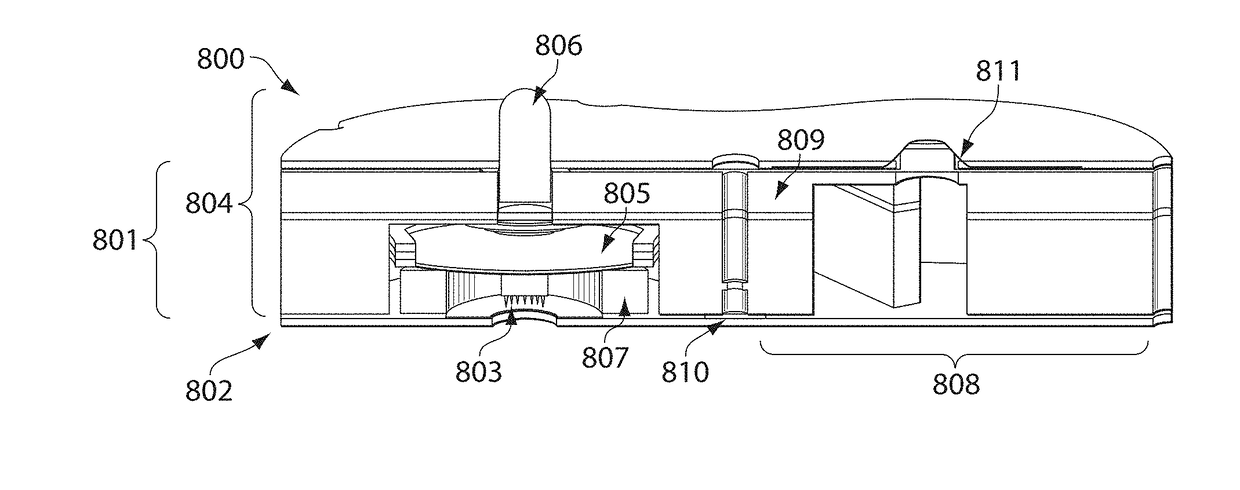
[0256]In this example, a fully integrated device was constructed for the withdrawal of a fluid from human subjects. A diagram of the device is shown in FIG. 13C. In this example, the integrated device 800 includes a support structure 801 for application to the skin of the subject. The structure is constructed from multiple layers of polyethylene terephthalate glycol (PETG). These layers may be formed into the requisite geometry by machining sheet stock or injection molding. The individual layers are bonded together using double-sided adhesive, such as 3M 1513 tape, but may also be bonded using non-adhesive methods such as ultrasonic welding or laser welding. The support structure is attached to the skin of a subject using an adhesive 802, such as Katecho 10G hydrogel.

[0257]The left side of the support structure in FIG. 13C houses the components necessary to insert a microneedle array into the skin. These components include a circular microneedle array of sixteen 750 micrometers long...


PUM


Abstract

The present invention generally relates to systems and methods for delivering and / or withdrawing a substance or substances such as blood or interstitial fluid, from subjects, e.g., from the skin and / or from beneath the skin. In one aspect, the present invention is generally directed to devices and methods for withdrawing or extracting blood from a subject, e.g., from the skin and / or from beneath the skin, using devices containing a fluid transporter (for example, one or more microneedles), and a storage chamber having an internal pressure less than atmospheric pressure prior to receiving blood. In some cases, the device may be self-contained, and in certain instances, the device can be applied to the skin, and activated to withdraw blood from the subject. The device, or a portion thereof, may then be processed to determine the blood and / or an analyte within the blood, alone or with an external apparatus. For example, blood may be withdrawn from the device, and / or the device may contain sensors or agents able to determine the blood and / or an analyte suspected of being contained in the blood. Other aspects of the present invention are directed at other devices for withdrawing blood (or other bodily fluids, e.g., interstitial fluid), kits involving such devices, methods of making such devices, methods of using such devices, and the like.

Description

RELATED APPLICATIONS[0001]This application claims the benefit of U.S. Provisional Patent Application Ser. No. 61 / 294,543, filed Jan. 13, 2010, entitled “Blood Sampling Device and Method,” by Chickering, et al.; U.S. Provisional Patent Application Ser. No. 61 / 334,533, filed May 13, 2010, entitled “Rapid Delivery and / or Withdrawal of Fluids,” by Chickering, et al.; U.S. Provisional Patent Application Ser. No. 61 / 334,529, filed May 13, 2010, entitled “Sampling Device Interfaces,” by Chickering, et al.; U.S. Provisional Patent Application Ser. No. 61 / 357,582, filed Jun. 23, 2010, entitled “Sampling Devices and Methods Involving Relatively Little Pain,” by Chickering, et al.; U.S. Provisional Patent Application Ser. No. 61 / 367,607, filed Jul. 26, 2010, entitled “Rapid Delivery and / or Withdrawal of Fluids,” by Davis, et al.; and U.S. Provisional Patent Application Ser. No. 61 / 373,764, filed Aug. 13, 2010, entitled “Clinical and / or Consumer Techniques and Devices,” by Chickering, et al. Ea...

Claims


Application Information

Patent Timeline
Patent Type & Authority Applications(United States)
IPC IPC(8): A61B5/00A61B5/15A61B5/145A61B5/151A61B5/157
CPCA61B5/150977A61B5/14532A61B5/15186A61B5/15144A61B5/15125A61B5/15117A61B5/15113A61B5/15105A61B5/150984A61B5/150969A61B5/150755A61B5/150503A61B5/150412A61B5/150389A61B5/150297A61B5/150229A61B5/150221A61B5/150099A61B5/150022A61B5/6849A61B5/685A61B5/157A61B5/150236A61B5/150244
Inventor CHICKERING, III, DONALD E.DAVIS, SHAWNHAGHGOOIE, RAMINBERNSTEIN, HOWARDLEVINSON, DOUGLAS A.MICHELMAN, MARK
Owner YOURBIO HEALTH INC
Why Eureka
Try Eureka