Staged deployment for electrical charge spots

a technology of electrical charging and staged deployment, which is applied in the direction of charging stations, electric vehicles, electrical apparatus, etc., can solve the problems of affecting the service life of electric vehicles, so as to reduce the time of infrastructure disturbance, facilitate the mate, and reduce the effect of manufacturing costs

Active Publication Date: 2011-10-11
CHARGE PEAK
View PDF199 Cites 72 Cited by
  • Summary
  • Abstract
  • Description
  • Claims
  • Application Information

AI Technical Summary

Benefits of technology

[0008]In order to overcome the above described drawbacks, a network of charge spot infrastructure adapters is deployed during a first stage. This first stage involves connecting the infrastructure adapters to a main power grid, which may include removing walls, digging, etc. Then in some embodiments, many of the adapters are covered for protection until they are required. During a second stage at least some of the infrastructure adapters are coupled to external units to create complete charge spots. As the demand for charge spots increases, more external units are coupled to the infrastructure adapters. The adapter includes an interface that easily mates an interface on the external units. The interfaces are universal such that any external unit can be mated to any adapter. Thus, the system can easily expand in response to demand until all of the adapters have been connected to external units. Furthermore, because of the universal interfaces, the external units are quick and easy to install and replace.
[0024]The advantages of the above described embodiments are numerous. Because the infrastructure of deployment can vary drastically from region to region (e.g. there are different deployment practices and local regulations in different countries), deploying charge spots as entire units would require developing units specific to the infrastructure in which they are deployed. However, according to the above embodiments, only the relatively simple infrastructure adapter needs to be specially designed to comport with the infrastructure. Then the more complicated external device can be a standard component that will easily mate with any infrastructure adapter. As such, the external units can be mass produced to cut down on manufacturing costs. Furthermore, the interfaces between the infrastructure adapter and the external unit are easy to plug into mate together interfaces. They do not require wiring to connect to each other. A relatively un-skilled operator can deploy the external units, and need not use any particular tools save for a simple screwdriver to install an external unit onto an infrastructure adapter.
[0025]Additionally, installing infrastructure adapters may require skilled operators to install them. Limiting the number of hours spent by skilled operators is therefore desirable. Infrastructure adapter installation may also require relatively drastic changes to the installation site, such as excavating, installing a conductor in a trench, placing the foundation etc. As such, limiting the number of times that the installation site must be disturbed is highly desirable. Using the methods described herein, a plurality of infrastructure adapters can be installed simultaneously, which cuts down on skilled operator time as well as limiting the time that an infrastructure is disturbed. In fact, it is desirable that more infrastructure adapters are installed than would be necessary for currently needed charge spots. As such, only some of the infrastructure adapters will be connected to external units to make functioning charge spots. The remaining infrastructure adapters will be covered with a temporary housing. At a later date, these infrastructure adapters will be uncovered and attached to additional external units. Installing these additional external units does not affect the already functioning charge spots. As such, more charge spots can be easily and inexpensively added as demand for charge spots increases.

Problems solved by technology

Unfortunately, fossil fuels, like gasoline which is typically used to power such vehicles, have numerous drawbacks including: a dependence on limited sources of fossil fuels; foreign sources of fossil fuels are often in volatile geographic locations; and such fuels produce pollution and likely climate change.
However, gasoline-electric hybrid vehicles do not eliminate the need for fossil fuels, as they still require an internal combustion engine in addition to the electric motor.
Bio-fuels, however, are currently expensive and years away from widespread commercial use.
However, connecting each charge spot to an electric power grid can be costly and time consuming.
Furthermore, the deployment often requires an operator with specialized skills.
Similarly, if the charge spot malfunctions or is vandalized, replacement of the charge spot is also costly, time consuming, and requires specialized operator skill.

Method used


Image

  • Staged deployment for electrical charge spots
  • Staged deployment for electrical charge spots
  • Staged deployment for electrical charge spots

Examples


Embodiment Construction

[0034]Reference will now be made in detail to embodiments, examples of which are illustrated in the accompanying drawings. In the following detailed description, numerous specific details are set forth in order to provide a thorough understanding of the present invention. However, it will be apparent to one of ordinary skill in the art that the present invention may be practiced without these specific details. In other instances, well-known methods, procedures, components, circuits, and networks have not been described in detail so as not to unnecessarily obscure aspects of the embodiments.

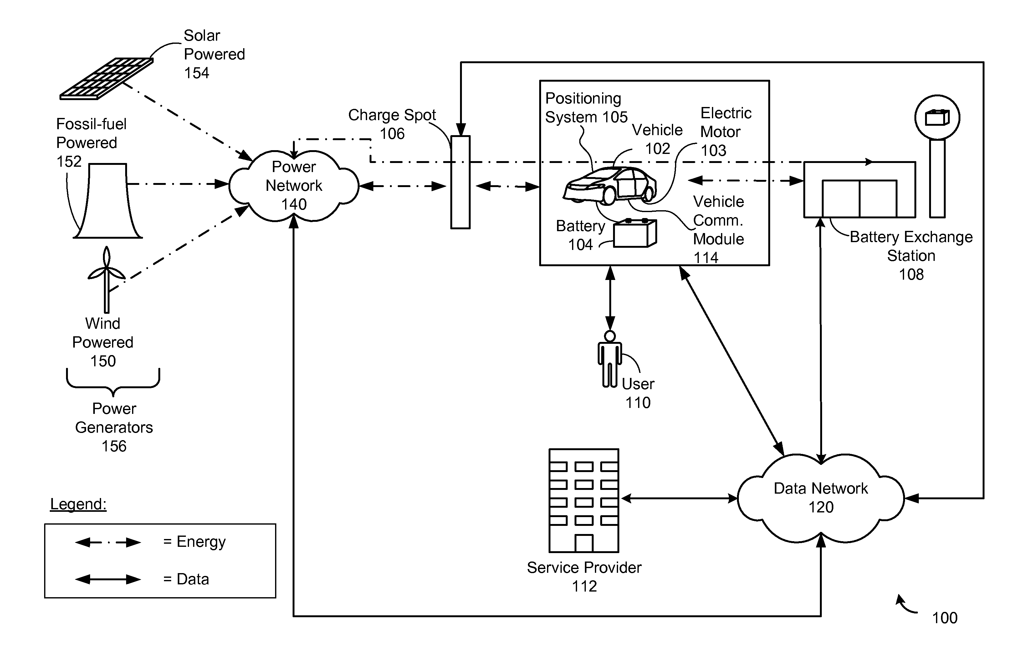
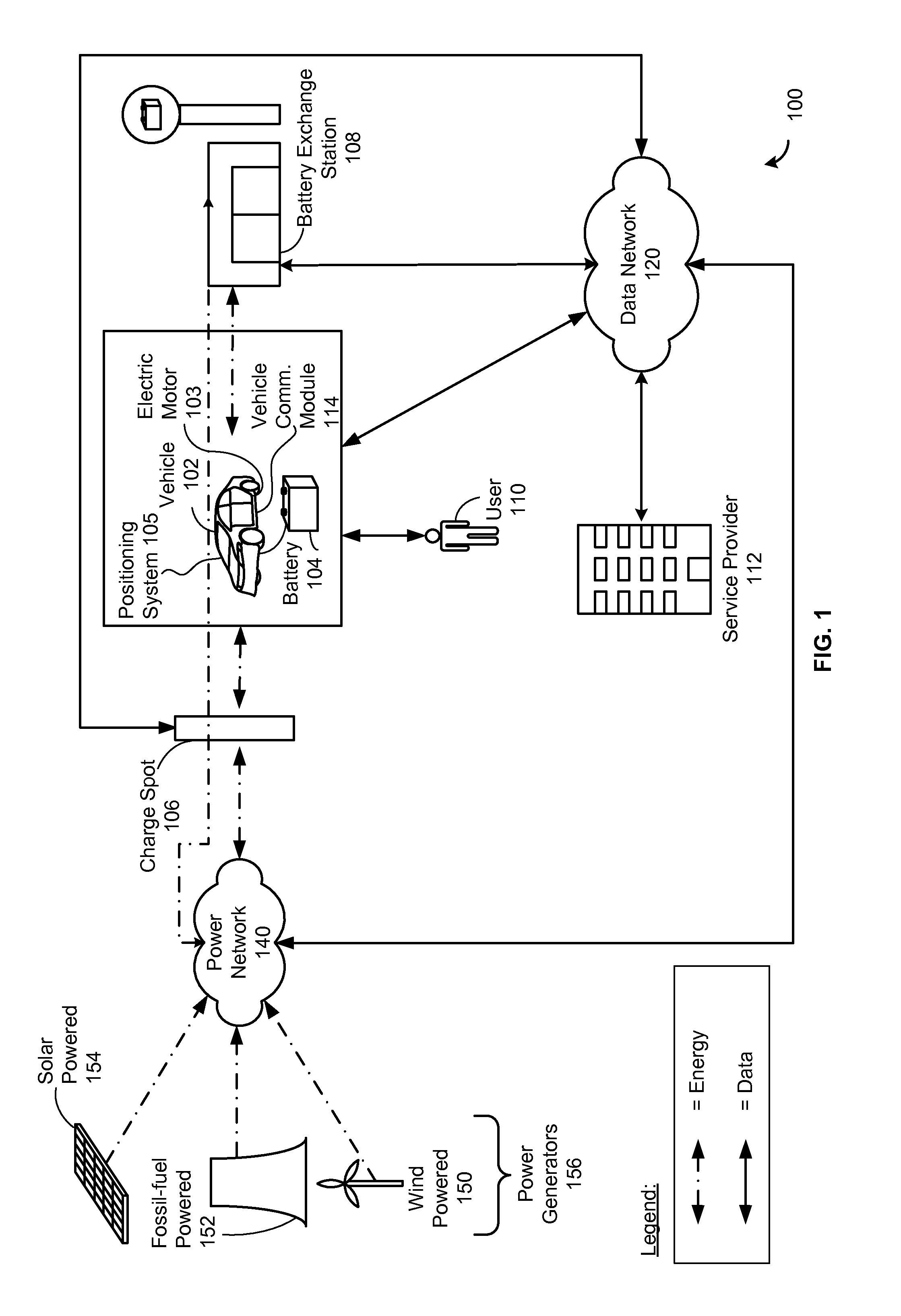
[0035]FIG. 1 illustrates an electric vehicle network 100, according to some embodiments. The electric vehicle network 100 includes a vehicle 102 and a battery 104. In some embodiments, the battery 104 includes any device capable of storing electric energy such as batteries (e.g., lithium ion batteries, lead-acid batteries, nickel-metal hydride batteries, etc.), capacitors, reaction cells (e.g., Zn...


PUM


Abstract

A method and system is provided to deploy electrical charge spots in stages according to demand. During a first stage a plurality of infrastructure adapters are installed. This may involve demolishing and rebuilding portions of the infrastructure and laying down power cables from the electrical power supply to the charge spot locations. The infrastructure adapters are then coupled to an electrical power supply. Many if not all of the infrastructure adapters are covered with a temporary housing protecting them from vandalism and weather. During a second stage, in response to a demand for charge stations, the charge stations are completed. During the second stage, at least one external unit is attached to an infrastructure adapter by making an infrastructure adapter quick connect interface with an external unit quick connect interface. As such, a charge spot is completed quickly in response to demand.

Description

RELATED APPLICATIONS[0001]This application is related to application Ser. No. 12 / 428,932, Filed Apr. 23, 2009, entitled “Electric Vehicle Battery System” and application Ser. No. 12 / 560,337, filed Sep. 15, 2009, entitled “System and Method for Operating an Electric Vehicle,” each of which is incorporated by reference herein in its entirety.TECHNICAL FIELD[0002]The disclosed embodiments relate generally to electric vehicle charge spots. In particular, the disclosed embodiments relate to an expandable system for deploying and replacing of electric vehicle charge spots by means of a fast connector.BACKGROUND[0003]Vehicles (e.g., cars, trucks, planes, boats, motorcycles, autonomous vehicles, robots, forklift trucks, etc.) are an integral part of the modern economy. Unfortunately, fossil fuels, like gasoline which is typically used to power such vehicles, have numerous drawbacks including: a dependence on limited sources of fossil fuels; foreign sources of fossil fuels are often in volat...

Claims


Application Information

Patent Timeline
Patent Type & Authority Patents(United States)
IPC IPC(8): H02J7/00B60K1/00
CPCB60L11/1818B60L11/1825B60L11/1846B60L11/185B60L2230/16Y02T10/7005Y02T10/7088Y02T90/121Y02T90/128Y02T90/14Y02T90/163Y02T90/169Y04S30/14B60L53/16B60L53/31B60L53/65B60L53/11B60L53/305Y02T10/70Y02T10/7072Y02T90/12Y02T90/16Y02T90/167H02J7/00
Inventor GENZEL, ERANSADOT, AVNERHANUNA, SHAULBAHAR, DALIT
Owner CHARGE PEAK
Why Eureka
Try Eureka