

Wireless communication system
a communication system and wireless technology, applied in the field of wireless communication system, can solve the problems of reducing the efficiency of the whole network, waste of data traffic, and ineffectiveness of mobile ip system, and achieve the effect of shortening the cessation time of information communication and changing a base station more inexpensively
- Summary
- Abstract
- Description
- Claims
- Application Information
AI Technical Summary
Benefits of technology
Problems solved by technology
Method used
Image

Examples
first embodiment
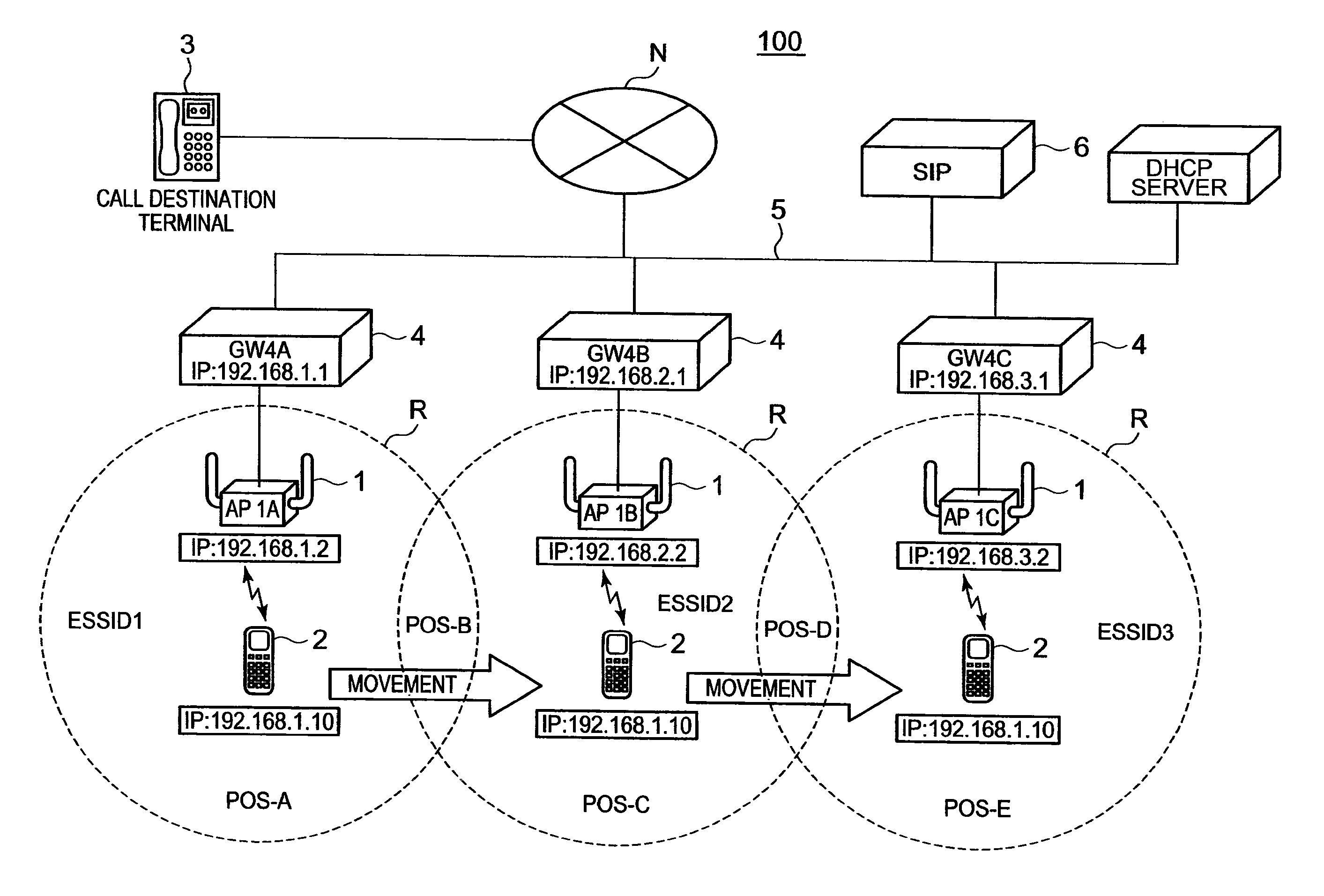
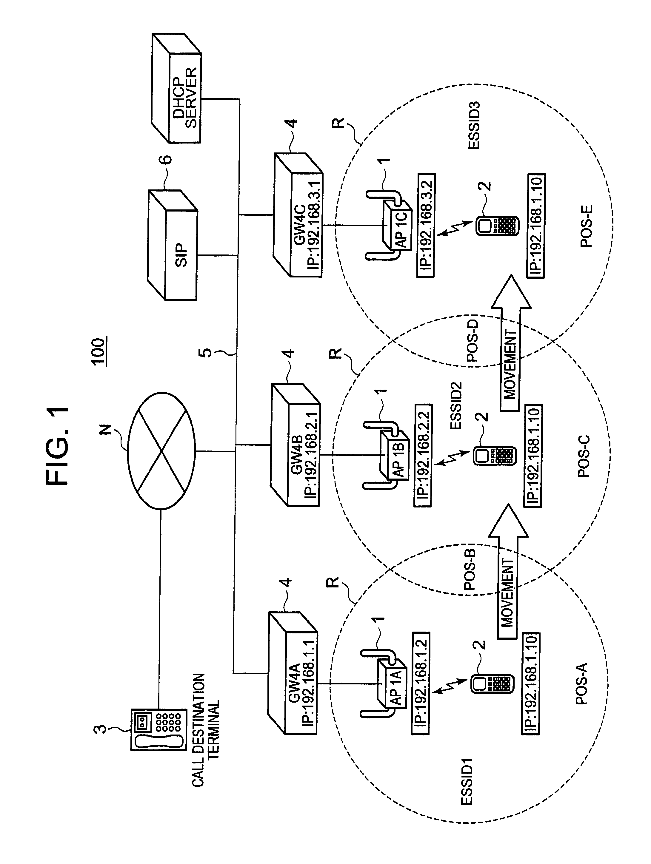
[0038]FIG. 1 is a view schematically showing the configuration of an IP telephone system 100 exemplified as a suitable example of the wireless communication system of a first embodiment, to which the present invention is applied.
[0039]The IP telephone system (wireless communication system) 100 according to the first embodiment performs a call (communication) without stopping it while the IP telephone terminal 2 is carried by a user or the like to move between different subnetworks from a position A (POS-A) to a position E (POS-E) with carrying on a communication with a call destination terminal 3. Such a continuous communication is performed by a handover processing for changing an access point 1 to be wirelessly connected to the IP telephone terminal 2.
[0040]To put it concretely, the IP telephone system 100 is composed of, as shown in FIG. 1, a plurality of access points (AP's) 1 (a first to a third access points 1A, 1B and 1C in FIG. 1), the IP telephone terminal 2 connected to an...
first modified example
[0145]In the following, the IP telephone system of a first modified example is described with reference to FIGS. 11-16.
[0146]FIGS. 11 and 12 are diagrams showing an example of the operation pertaining to the handover processing by the IP telephone system of the first modified example. FIG. 13 is a block diagram of an access point 201. FIG. 14 is a diagram illustrating the execution timing of handover by the IP telephone system of the first modified example. FIG. 15 is a block diagram of the IP telephone terminal 202.
[0147]Because the IP telephone system of the first modified example is almost the same as the first embodiment described above except for the configuration of the access point 201 and the execution of the designating processing of a handover destination, the similar components are denoted by the same reference marks and their descriptions are omitted.
[0148]The IP telephone system of the first modified example performs the designation of a handover destination and the ins...
second embodiment
[0190]In the following an IP telephone system 300 of a second embodiment is described with reference to FIGS. 17-20.
[0191]FIG. 17 is here a view schematically showing the schematic configuration of the IP telephone system 300 of the second embodiment to which the present invention is applied. Moreover, FIG. 18 is a block diagram of an access point 301.
[0192]Because the IP telephone system 300 of the second embodiment is almost the same as that of the first embodiment mentioned above except for the configuration of the access point 301, the similar components are denoted by the same reference marks and their descriptions are omitted.
[0193]The access point 301 of the IP telephone system 300 of the second embodiment is wirelessly connected to an IP telephone terminal 302 through a provisional subnetwork by performing a probe response of the same provisional identifier as that of the subnetwork to which the initial access point is connected to a probe request from the IP telephone termi...
PUM
 Abstract
Description
Claims
Application Information