Radio frequency (RF) signal generator and method for providing test signals for testing multiple RF signal receivers

a receiver technology, applied in the field of system and method for testing multiple radio frequency (rf) signal receivers, can solve the problems of adding system costs, complicating the testing, and not being considered a reliable signal sour

Inactive Publication Date: 2011-10-11
LITEPOINT CORP
View PDF8 Cites 17 Cited by
  • Summary
  • Abstract
  • Description
  • Claims
  • Application Information

AI Technical Summary

Problems solved by technology

However, particularly as an increasing number of DUTs 16 is to be tested, this type of test implementation has a number of problems relating to mutual power differences among the different signals 15 feeding the DUTs 16.
This adds to system costs and complicates the testing due to the external control required, as well as the calibration of each signal path (e.g., cable plus attenuator).
However, as the GPS signals received in this manner will vary, e.g., with weather conditions, this cannot be considered a reliable signal source for testing noise figure, since the input signal level for a given satellite signal is not well defined.
Conventional multi-channel GPS signal generators, however, are more expensive than single-channel generators, thereby limiting their use to more expensive manufacturing requirements where repeatable locking to GPS signals must be tested.

Method used


Image

  • Radio frequency (RF) signal generator and method for providing test signals for testing multiple RF signal receivers
  • Radio frequency (RF) signal generator and method for providing test signals for testing multiple RF signal receivers
  • Radio frequency (RF) signal generator and method for providing test signals for testing multiple RF signal receivers

Examples


Embodiment Construction

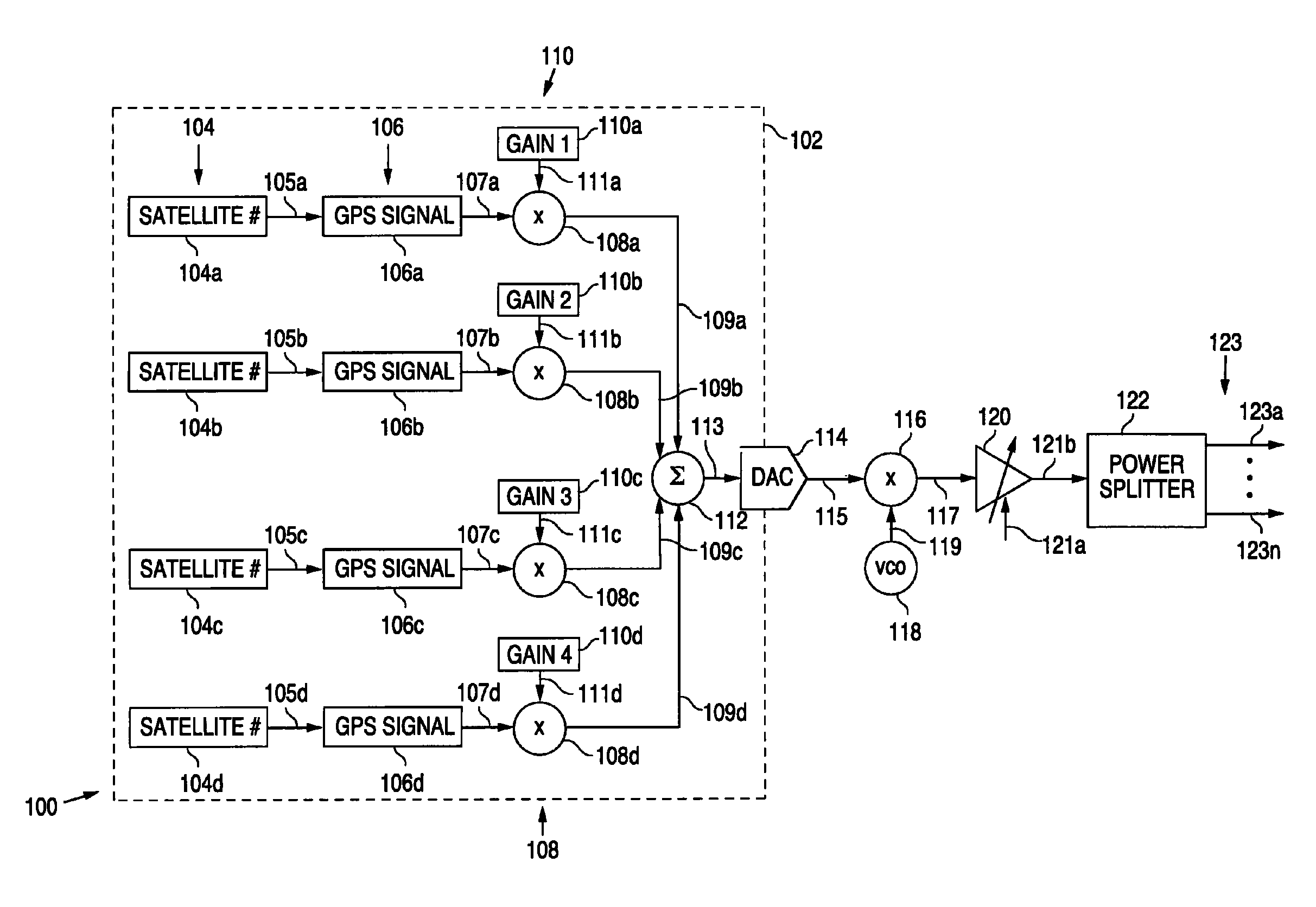
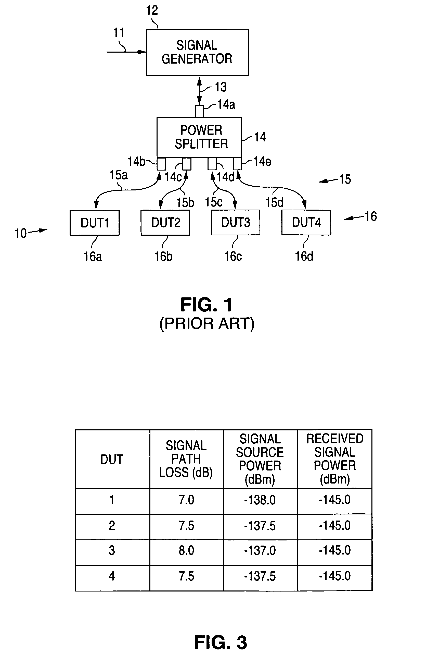
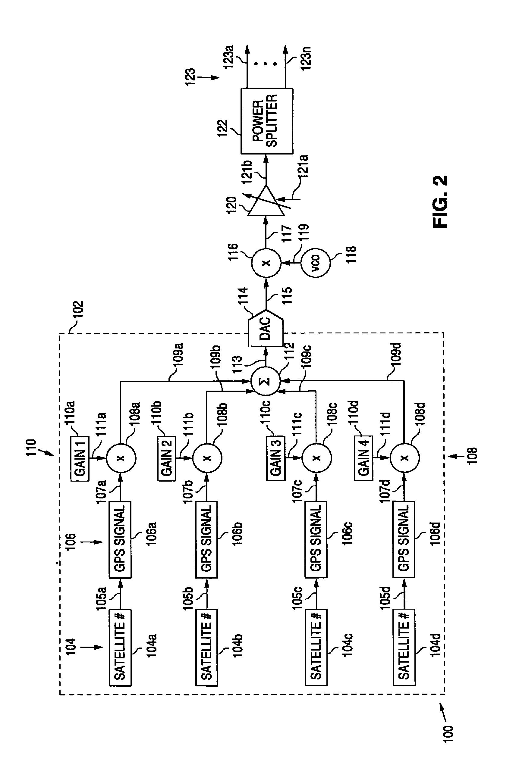
[0033]The following detailed description is of example embodiments of the presently claimed invention with references to the accompanying drawings. Such description is intended to be illustrative and not limiting with respect to the scope of the present invention. Such embodiments are described in sufficient detail to enable one of ordinary skill in the art to practice the subject invention, and it will be understood that other embodiments may be practiced with some variations without departing from the spirit or scope of the subject invention.

[0034]Throughout the present disclosure, absent a clear indication to the contrary from the context, it will be understood that individual circuit elements as described may be singular or plural in number. For example, the terms “circuit” and “circuitry” may include either a single component or a plurality of components, which are either active and / or passive and are connected or otherwise coupled together (e.g., as one or more integrated circ...


PUM


Abstract

A test signal interface and method for allowing sharing of multiple test signal generators among multiple devices under test (DUTs). Digital baseband test signals generated by the multiple test signal generators are combined and converted to a baseband analog signal for conversion to a radio frequency (RF) signal for testing the multiple DUTs.

Description

BACKGROUND[0001]1. Field of the Invention[0002]The present invention relates to a system and method for testing multiple radio frequency (RF) signal receivers, and in particular, to testing multiple RF signal receivers with a shared RF signal generator.[0003]2. Related Art[0004]Manufacturing test of receive-only RF signal systems, e.g., global position satellite (GPS) signal receivers, is often implemented by using a single RF signal source to be shared among multiple devices under test (DUTs). Generally, this is easily done, as the signal source typically need only provide a continuous signal, plus this has the advantage of reduced costs.[0005]Referring to FIG. 1, such a test implementation uses a common RF signal source 12 which receives one or more control signals 11 in accordance with which an output signal 13 is provided. This signal 13 is provided to a 1:N, e.g., 1:4, power splitter 14 which divides this signal 13 (in signal power) among its multiple output signals 15a, 15b, 1...

Claims


Application Information

Patent Timeline
Patent Type & Authority Patents(United States)
IPC IPC(8): H04B17/00
CPCG01S19/23
Inventor OLGAARD, CHRISTIAN VOLF
Owner LITEPOINT CORP
Why Eureka
Try Eureka