

Device and process for oscillation insulation in a transmission path
- Summary
- Abstract
- Description
- Claims
- Application Information
AI Technical Summary
Benefits of technology
Problems solved by technology
Method used
Image

Examples
Embodiment Construction
[0072]The particulars shown herein are by way of example and for purposes of illustrative discussion of the embodiments of the present invention only and are presented in the cause of providing what is believed to be the most useful and readily understood description of the principles and conceptual aspects of the present invention. In this regard, no attempt is made to show structural details of the present invention in more detail than is necessary for the fundamental understanding of the present invention, the description taken with the drawings making apparent to those skilled in the art how the several forms of the present invention may be embodied in practice.
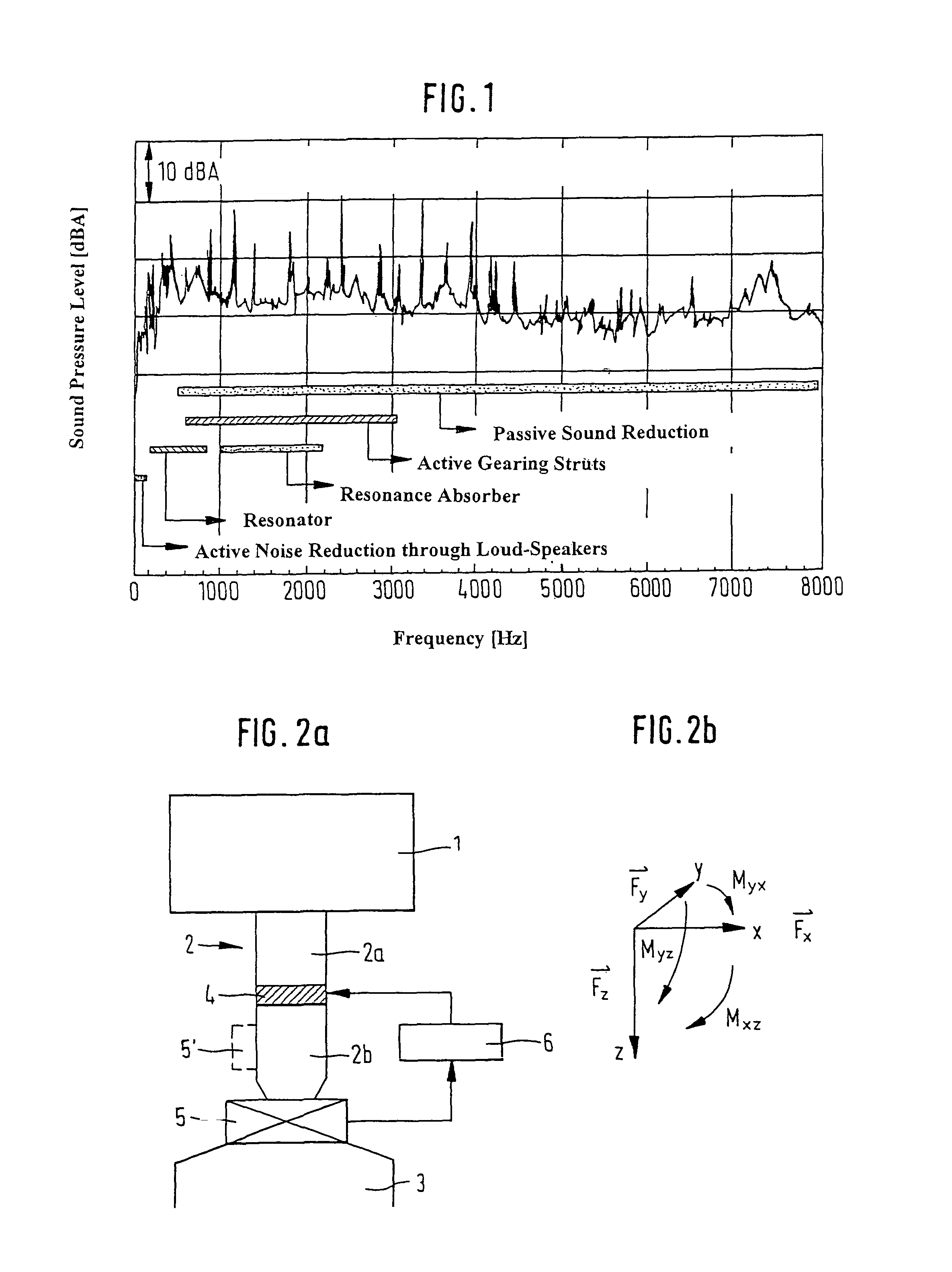
[0073]FIG. 1 shows the typical range of application of the invention in the frequency range between 500 Hz and 4000 Hz.
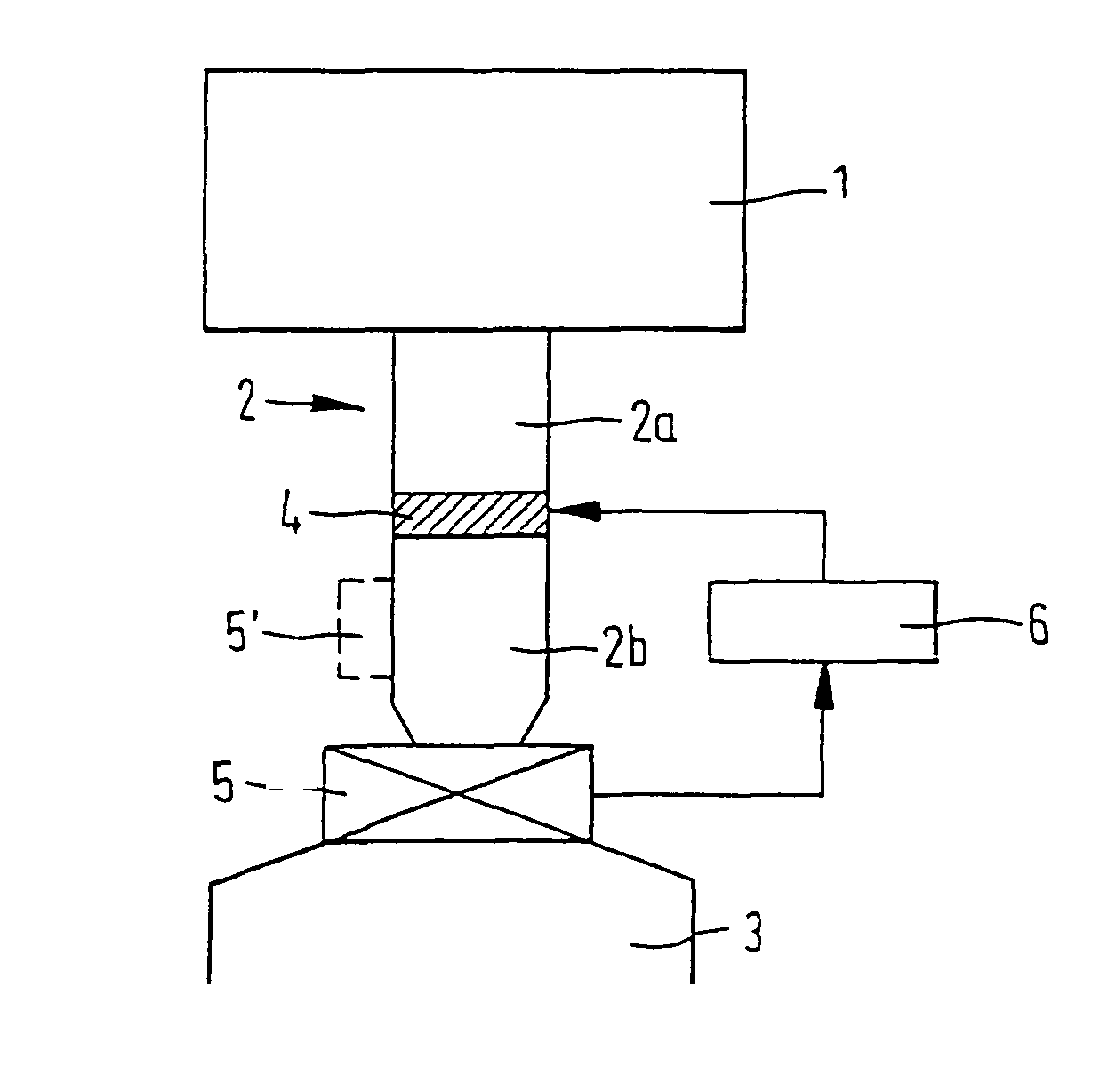
[0074]FIG. 2a shows in greatly schematized representation a device according to the invention for oscillation insulation in a transmission path. A first body 1 is hereby connected to a second body 3 via a...
PUM
 Abstract
Description
Claims
Application Information