Joint unit, preferably for mounting the chassis control arm of a motor vehicle

a technology for chassis control arms and joints, which is applied in the direction of mechanical equipment, couplings, transportation and packaging, etc., can solve the problems of conceivable special wear of bearing shells or pivot pins, and the failure of the total joint unit normally used

Inactive Publication Date: 2011-10-18
ZF FRIEDRICHSHAFEN AG
View PDF5 Cites 12 Cited by
  • Summary
  • Abstract
  • Description
  • Claims
  • Application Information

AI Technical Summary

Benefits of technology

[0010]Contrary to all the solutions of a securing unit that are known from the state of the art, the teaching according to the present invention provides a design solution, which can be fully accommodated within the usual structural dimensions of a joint unit. The special outfitting of such a joint unit with the additional securing unit is no longer visible in this manner from the outside, so that reservations on the part of the users and vehicle owners are no longer to be feared.
[0011]Another embodiment of the blocking element makes provisions, for example, for this blocking element to have at least two projections projecting symmetrically over the cross section of the securing bolt. Projections may be designed in the form of an end web at the free end of the securing bolt. The securing bolt is fixed, on the whole, at the housing or pivot pin belonging to it by a screw connection. In addition, other possibilities of fastening are, of course, conceivable as well. The shape of the blocking element in conjunction with the elongated shape of the securing bolt offers a simple possibility of creating an end component that cooperates with the securing mount, has a simple design and can be manufactured in a simple manner, at one free end of the securing bolt.
[0012]In conjunction with the special design of the securing bolt, the securing mount has limiting surfaces, which are directed towards the inside of the joint unit and extend behind the above-described blocking element. The securing mount may additionally have an insertion opening directed towards the inside of the joint unit for a securing bolt; the cross section of the insertion opening being essentially rectangular, the greater lateral dimension of the rectangular cross section permitting the passage of the blocking element of the securing bolt through the insertion opening and the other lateral dimension of the rectangular cross section being selected to be smaller than the breadth of the projections of the blocking element. A so-called bayonet connection, in which the securing bolt is turned by an amount of, for example, 90° after being passed through the insertion opening of the securing mount, is formed due to this design, and an axial motion of the bolt is then prevented from occurring by the limiting surfaces present within the securing mount, so that separation between the housing and the securing bolt fastened to the pivot pin will then be prevented from occurring as well.
[0014]Moreover, an advantageous variant of the subject of the present invention for special applications provides for manufacturing the housing as a cast component, in which case the securing mount is integrated as a recess and the limiting surfaces with their cooperating function with the blocking element of the securing bolt are inserted as separate sheet metal elements into the recess of the housing. Such an embodiment may bring about a more cost-effective manufacture of the joint unit under certain general conditions.

Problems solved by technology

Nevertheless, events or highly unfavorable causal relationships are conceivable, in which total failure of the joint units usually used may occur.
For example, special wear of the bearing shell or of the pivot pin is conceivable, which may occur due to failure of the sealing systems used in such joint units, because dirt or water enters the interior of the joint.
Complete separation of the unity between the housing and the pivot pin of the damaged joint unit would be the most serious consequence of such failure of the joint units.
However, the visual presence of the objectively desirable and necessary securing system causes a joint unit to be subjectively present for the user, which may not necessarily suggest, owing to its special embodiment, the safety of a joint unit, which would be provided with a redundant securing unit invisible from the outside.

Method used


Image

  • Joint unit, preferably for mounting the chassis control arm of a motor vehicle
  • Joint unit, preferably for mounting the chassis control arm of a motor vehicle
  • Joint unit, preferably for mounting the chassis control arm of a motor vehicle

Examples


Embodiment Construction

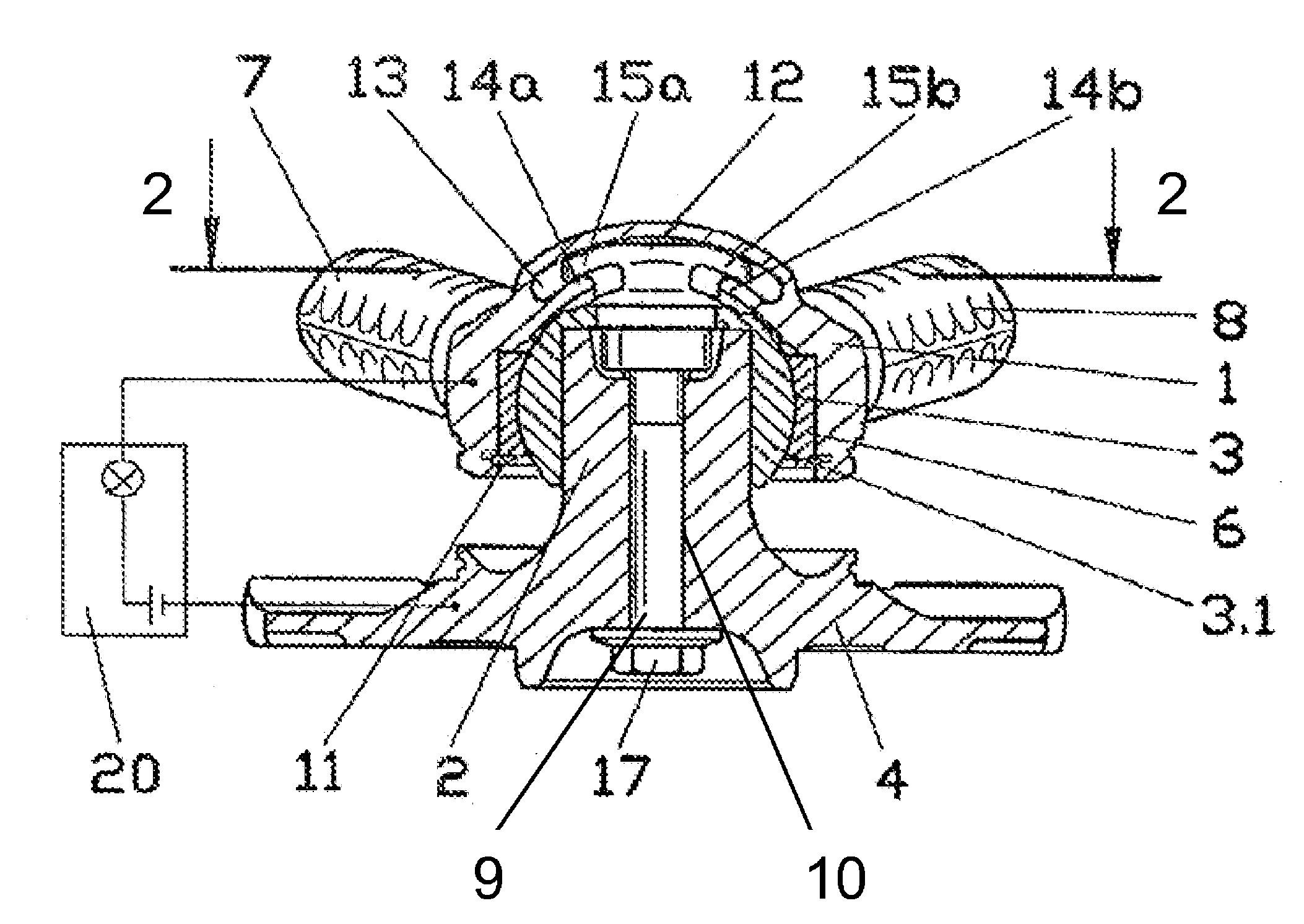
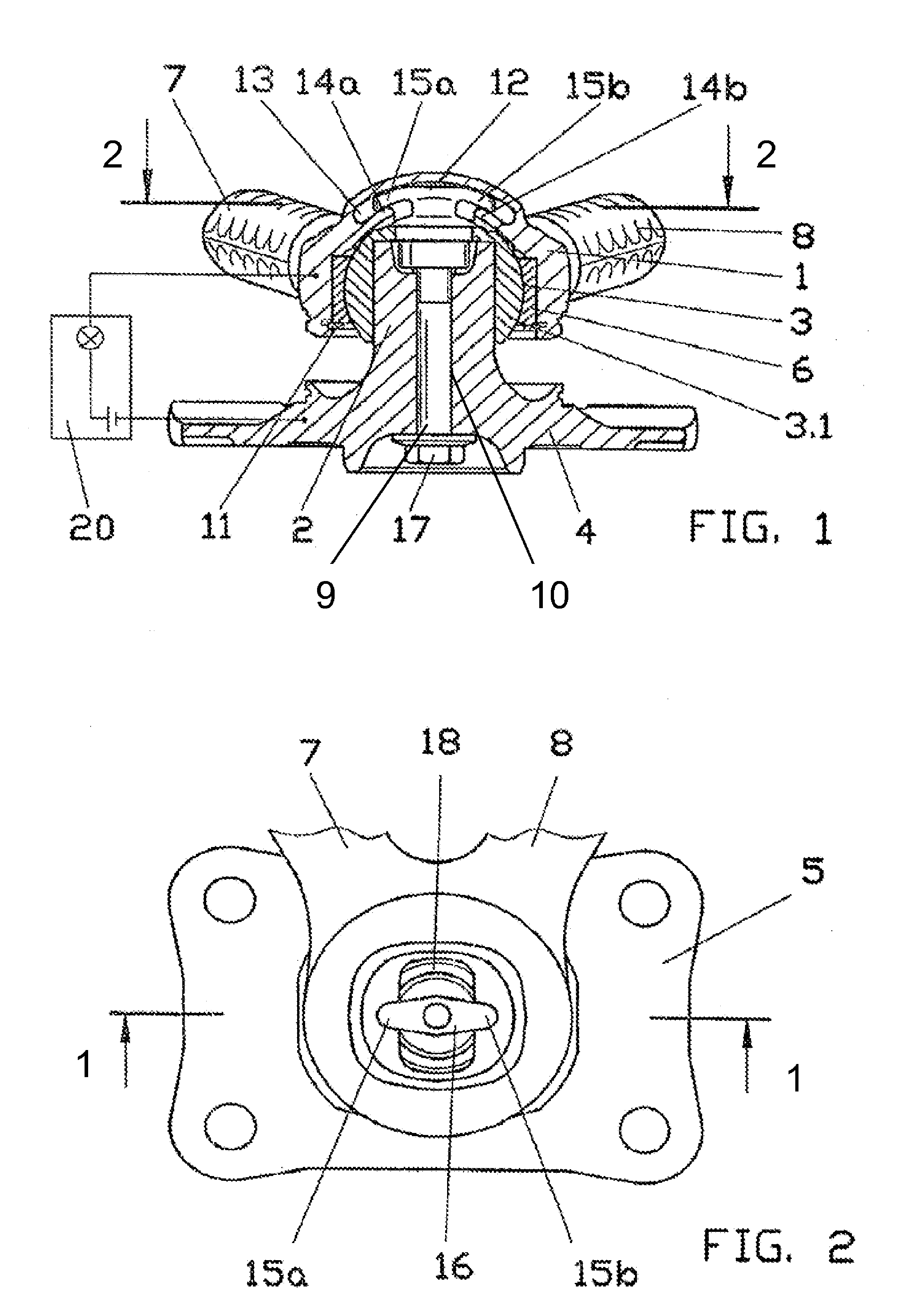
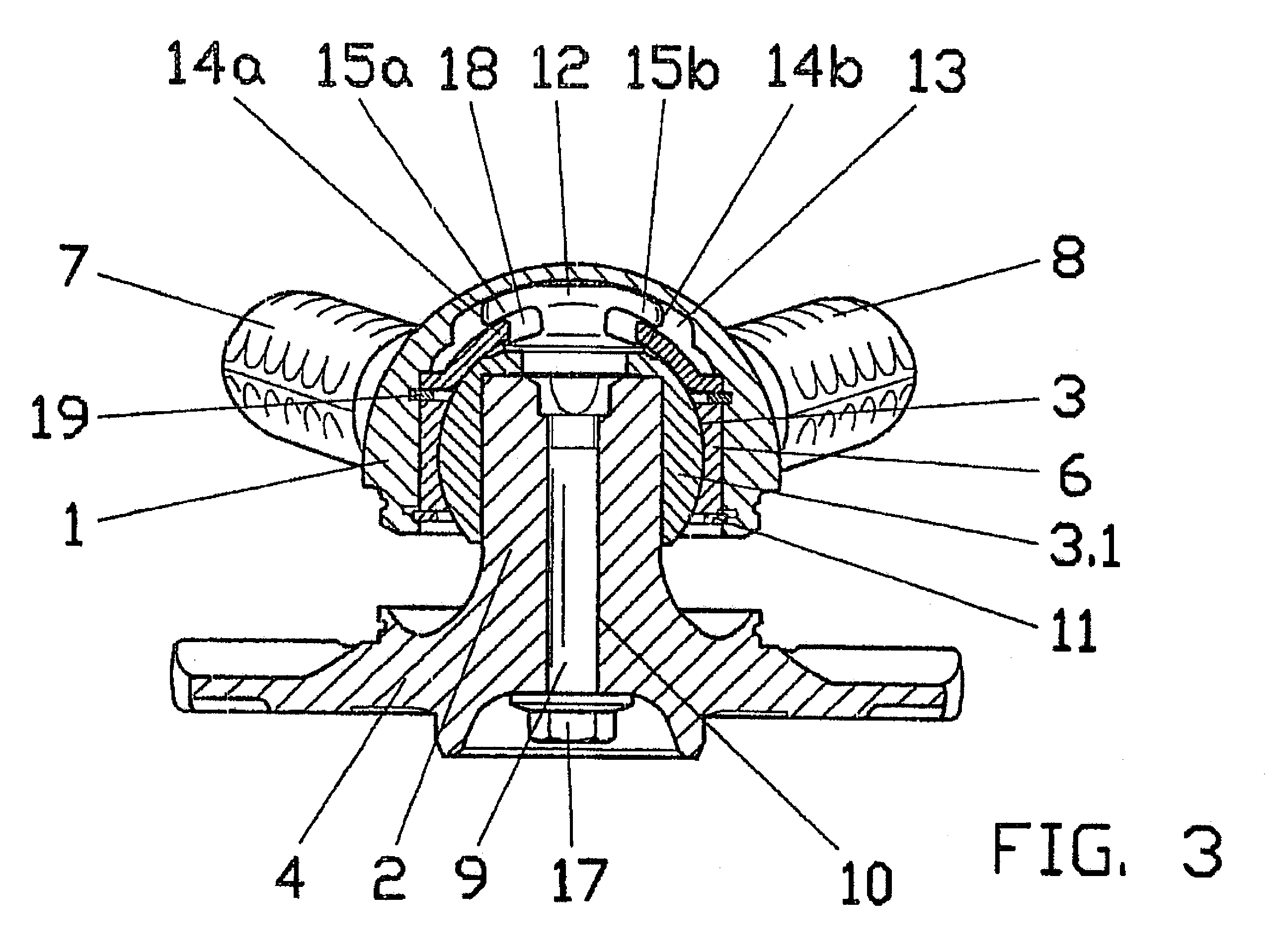
[0022]Referring to the drawings in particular, the essential features according to the present invention are explained with reference to an exemplary embodiment and an embodiment variant according to the present invention. The exemplary embodiment is shown in FIG. 1, and an embodiment variant is shown in FIG. 3. Uniform reference numbers will be used below in the individual figures insofar as they are used for identical components or assembly units.

[0023]The joint unit in FIG. 1 has a housing 1, with which the connection area of a control arm pair 7, 8 of a steering triangle for a motor vehicle is made integrally in one piece.

[0024]In the design being shown as an embodiment open on one side, housing 1 has an inner cavity, into which a bearing shell 6 is inserted. The bearing shell makes possible within the joint unit a vibration-damping function, which at the same time possesses sliding properties. Bearing shell 6 receives, when viewed towards the interior of the joint, the spheroid...


PUM


Abstract

A joint unit such as for mounting the vehicle control arm of a motor vehicle, is provided with a control arm-side housing (1), in which a pivot pin (2) is mounted pivotably by means of a spheroidal bearing surface (3), wherein the joint unit has a securing unit against the separation of the housing (1) from the pivot pin (2). The securing unit includes a securing bolt (9), arranged within the pivot pin (2) essentially in parallel to the central longitudinal axis of the pivot pin (2) and with a blocking element (12) at a free end. A securing mount (13) is located within the housing (1) or the pivot pin (2) and in this the blocking element (12) is mounted in a contactless manner in the mounted state of the joint unit. The securing mount (13) is part of the securing unit, and the securing bolt (9) is fixed to the component of the joint unit (housing (1) or pivot pin (2)) that is not provided with the securing mount (13). Redundant securing of a joint unit against separation of the housing (1) from the pivot pin (2), which is not visible from the outside and is thus advantageous from both a safety engineering viewpoint and a visual viewpoint is achieved.

Description

CROSS REFERENCE TO RELATED APPLICATIONS[0001]This application is a United States National Phase application of International Application PCT / DE2007 / 001420 and claims the benefit of priority under 35 U.S.C. §119 of German Patent Application DE 10 2006 039 863.7 filed Aug. 25, 2006, the entire contents of which are incorporated herein by reference.FIELD OF THE INVENTION[0002]The present invention pertains to a joint unit, preferably for mounting the chassis control arm of a motor vehicle, with a control arm-side housing, in which a pivot pin is mounted pivotably by means of a spheroidal bearing surface, wherein the joint unit has a securing unit against the separation of the housing and the pivot pin.BACKGROUND OF THE INVENTION[0003]Wheel suspensions in motor vehicles have different bearings and joints in terms of function depending on the requirements. The joints are used, for example, to make possible a relative motion of two components in a plurality of degrees of freedom. Moreover...

Claims


Application Information

Patent Timeline
Patent Type & Authority Patents(United States)
IPC IPC(8): B62D7/16
CPCB60G7/005F16C11/106B60G2204/11B60G2204/416B60G2206/8207Y10T403/32204Y10T403/32852Y10T403/32631Y10T403/32639B60G2800/80F16C2326/05F16C11/0609F16C11/0628F16C11/0661B60G7/02B60G7/00F16C11/06
Inventor KNOPP, SORENBUHL, MANFREDKUNZE, RALF
Owner ZF FRIEDRICHSHAFEN AG
Why Eureka
Try Eureka