Manual power sander, and vibration isolation device of a manual power sander

a technology of vibration isolation device and power sander, which is applied in the direction of grinding drive, manufacturing tools, portable power-driven tools, etc., can solve the problems of user fatigue, unfavorable sanding operation, and increased vibration, so as to achieve greater contact pressure, improve the effect of sanding operation and reduce the number of users

Inactive Publication Date: 2011-10-18
ROBERT BOSCH GMBH
View PDF23 Cites 1 Cited by
  • Summary
  • Abstract
  • Description
  • Claims
  • Application Information

AI Technical Summary

Benefits of technology

[0004]In a manual power sander of the invention, in particular an orbital sander, at least one handle is joined to a housing via at least one vibration isolation element. In the housing, there is at least one drive unit for driving a platelike tool holder, in which a sander plate, located in a sander plate plane, is secured. The contact pressure of the tool holder against the workpiece required for the sanding can be initiated by the user via the handle. By varying the contact pressure exerted by the user, the sanding operation can be controlled; with greater contact pressure, the workpiece is machined more intensively, and vice versa. The contact pressure is effected in a force direction that is substantially perpendicular to the sander plate plane. The handle is favorably located above the sander plate plane. Advantageously, by the proposed embodiment, the housing is isolated from the handle, so that unpleasant vibration at the handle can be reduced.

Problems solved by technology

In the operation of such hand-guided power sanders, because of the oscillation of the working unit, unpleasant vibration arises, especially in the region of the handle.
Such vibration leads to user fatigue sooner and to a lessening of the holding forces.
Particularly in long-term operation, a user can be exposed to an increased risk to health.
A disadvantage here, however, is that working with the hand sander, especially on a wall or overhead, is more difficult because of the great weight.

Method used


Image

  • Manual power sander, and vibration isolation device of a manual power sander
  • Manual power sander, and vibration isolation device of a manual power sander
  • Manual power sander, and vibration isolation device of a manual power sander

Examples


Embodiment Construction

[0025]Identical elements are identified by the same reference numerals throughout the drawings.

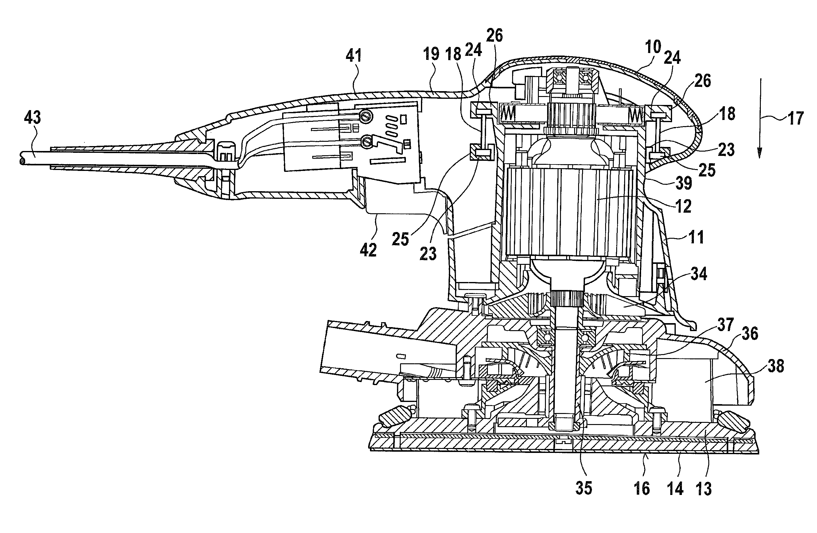
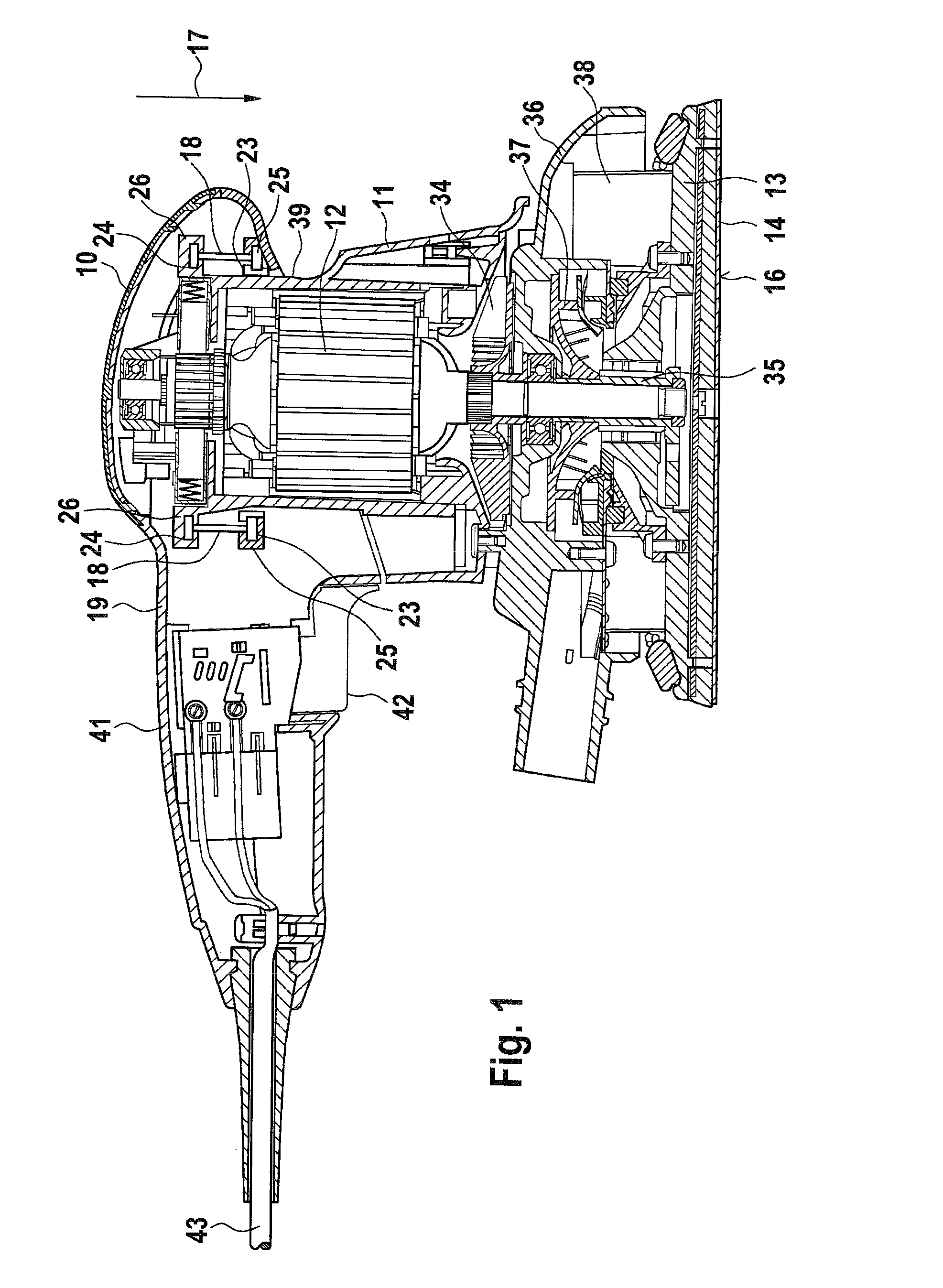
[0026]In FIG. 1, a preferred embodiment of a manual power sander is shown, which is embodied as an orbital sander and which has a housing 11, in which in the usual way there is a drive unit 12 of a platelike tool holder 13; the drive unit 12 is connected in terms of force to an eccentric 35. A sander plate 14 is secured in the tool holder 13 and is driven to execute circular motions via the eccentric 35. As the drive unit 12, it is also possible to use a compressed air turbine, a suction turbine, or a DC motor.

[0027]A motor fan 34 for ventilating the drive unit 12 is also provided in the housing 11. Between the tool holder 13 and the housing 11, there is an extraction hood 36, in which a dust fan 37 is located. The tool holder 13 is secured to the extraction hood 36 via rocker legs 38. For vibration reduction, a compensatory weight is provided, which is part of the eccentric 35 and is not ...


PUM


Abstract

The invention emanates from a hand-held grinder, in particular an orbital grinder, with at least one handle (10) in or on a housing part (19) and with a drive unit (12) to drive a grinding disc (14) in or on a disc-shaped tool carrier (13) in a housing (11), wherein the grinding disc (14) is on a grinding disc plane (16) and the direction of force (17) is perpendicular to the plane (16) of the grinding disc. The invention proposes that the handle (10) is connected to the housing (11) through at least one vibration decoupling element (18, 71). The invention also relates to a vibration decoupling device of a hand-held grinder.

Description

CROSS-REFERENCE TO RELATED APPLICATION[0001]The invention described and claimed hereinbelow is also described in German Patent Applications DE 10 2006 025 862.2 of Jun. 2, 2006 and DE 10 2006 034 078.7 of Jul. 24, 2006. This German Patent Application, whose subject matter is incorporated here by reference, provides the basis for a claim of priority of invention under 35 U.S.C. 119(a)-(d).BACKGROUND OF THE INVENTION[0002]Hand-guided electric sanders, such as orbital sanders, eccentric sanders, delta sanders and the like, have a tool holder that moves for instance in a circular path in a single plane. In the operation of such hand-guided power sanders, because of the oscillation of the working unit, unpleasant vibration arises, especially in the region of the handle. Such vibration leads to user fatigue sooner and to a lessening of the holding forces. Particularly in long-term operation, a user can be exposed to an increased risk to health. To attain good vibration damping at adequate...

Claims


Application Information

Patent Timeline
Patent Type & Authority Patents(United States)
IPC IPC(8): B24B27/08B24B23/03
CPCB25F5/006B24B23/00
Inventor ROEHM, HEIKO
Owner ROBERT BOSCH GMBH
Why Eureka
Try Eureka