
Modular design for ophthalmic surgical probe

a technology of ophthalmological and surgical probes, applied in the field of microsurgical instruments, can solve the problems of less flexibility and the skin serving as both an ergonomic componen

Active Publication Date: 2011-10-18
ALCON INC
View PDF40 Cites 177 Cited by
  • Summary
  • Abstract
  • Description
  • Claims
  • Application Information

AI Technical Summary

Benefits of technology

This design enhances manufacturing flexibility, simplifies assembly, and allows conversion between multiple gage size probes using the same engine parts, improving the overall usability and adaptability of the vitrectomy probe.

Problems solved by technology

A disadvantage to this is that the skin serves as both an ergonomic component as well as a part that is responsible for function.
This results in less flexibility.

Method used


Image

  • Modular design for ophthalmic surgical probe
  • Modular design for ophthalmic surgical probe
  • Modular design for ophthalmic surgical probe

Examples


Embodiment Construction

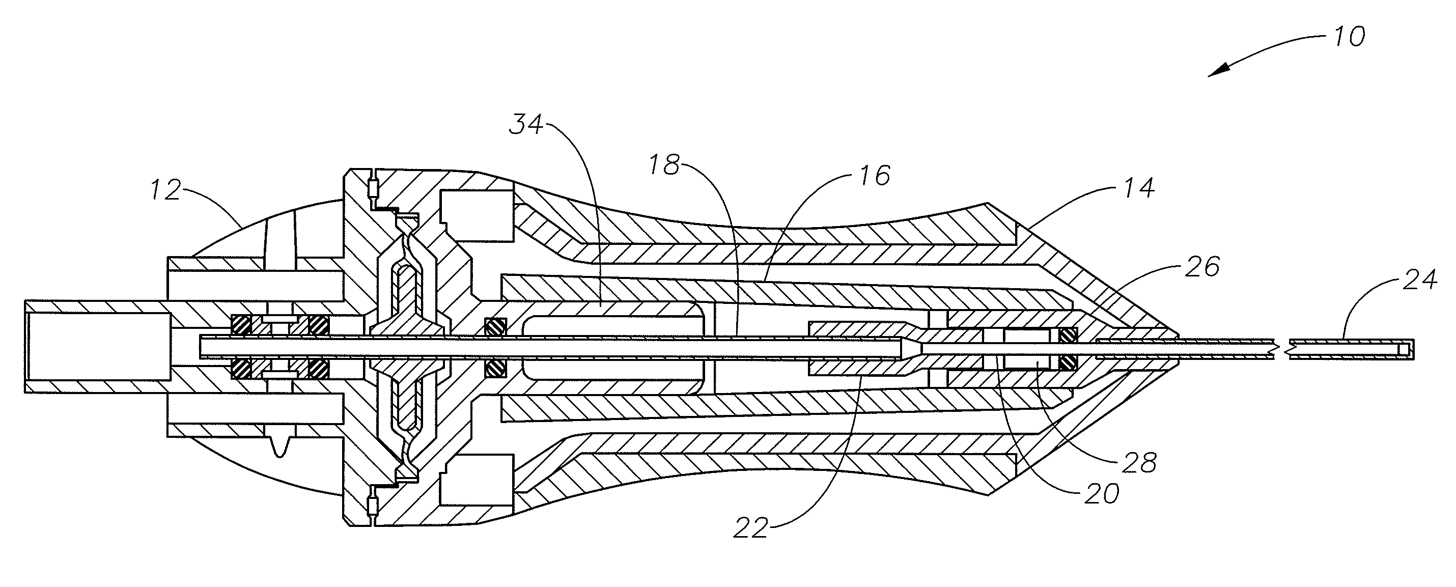
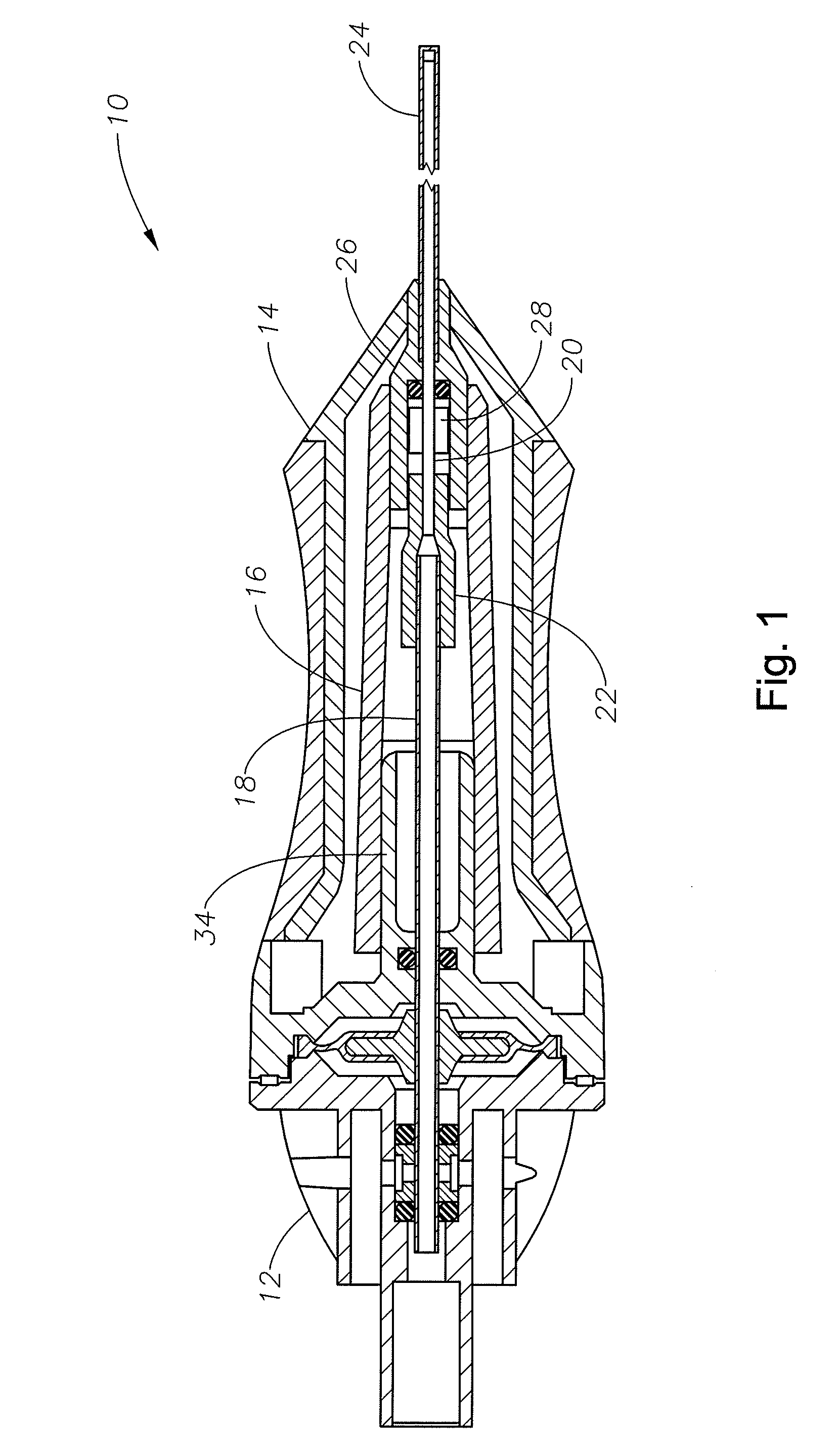
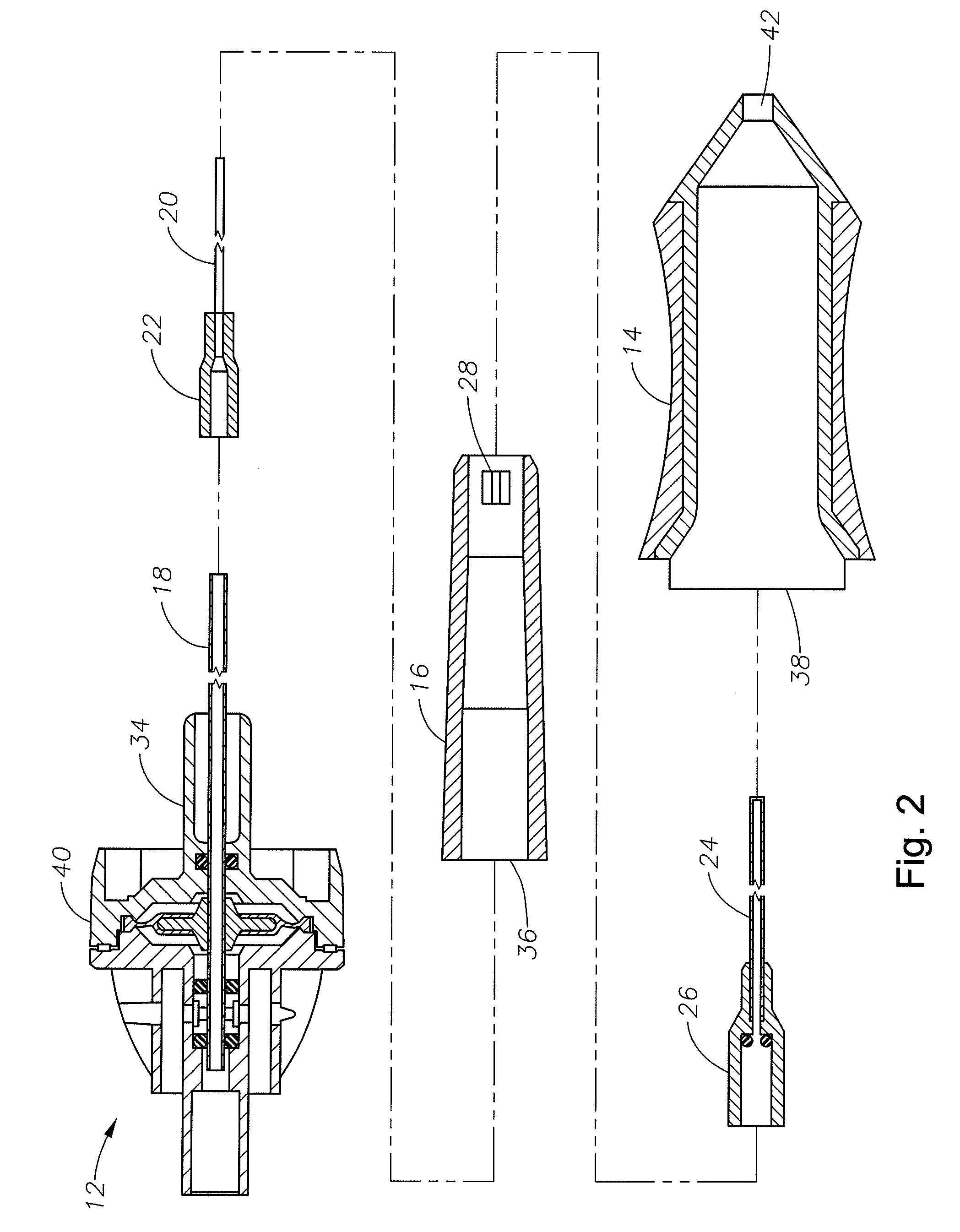
[0012]The preferred embodiments of the present invention and their advantages are best understood by referring to FIGS. 1-2 of the drawings, like numerals being used for like and corresponding parts of the various drawings.

[0013]Vitrectomy probe 10 consists of engine 12, shell or skin 14, needle holder 16, drive shaft 18, cutter 20, and needle 24. Although the ophthalmic surgical probe of the present invention is described herein in connection with a vitrectomy probe 10, the present invention is applicable to other ophthalmic or other surgical probes, instruments, and handpieces. Cutter coupling 22 is integrally formed on the proximal end of cutter 20. Needle coupling 26 is integrally formed on the proximal end of needle 24. Drive shaft 18 extends axially from engine 12. Distal end of drive shaft 18 removably engages cutter coupling 22 of cutter 20. Drive shaft support member 34 removably engages opening 36 of needle holder 16. Drive shaft support member 34, drive shaft 18, and cutt...


PUM


Abstract

An ophthalmic surgical probe having a modular drive assembly and a skin that is removable from the drive assembly. This design simplifies probe manufacturing and provides greater manufacturing flexibility.

Description

FIELD OF THE INVENTION[0001]The present invention generally pertains to microsurgical instruments. More particularly, but not by way of limitation, the present invention pertains to microsurgical instruments used in posterior segment ophthalmic surgery, such as vitrectomy probes.DESCRIPTION OF THE RELATED ART[0002]Many microsurgical procedures require precision cutting and / or removal of various body tissues. For example, certain ophthalmic surgical procedures require the cutting and / or removal of the vitreous humor, a transparent jelly-like material that fills the posterior segment of the eye. The vitreous humor, or vitreous, is composed of numerous microscopic fibers that are often attached to the retina. Therefore, cutting and removal of the vitreous must be done with great care to avoid traction on the retina, the separation of the retina from the choroid, a retinal tear, or, in the worst case, cutting and removal of the retina itself.[0003]The use of microsurgical cutting probes...

Claims


Application Information

Patent Timeline
Patent Type & Authority Patents(United States)
IPC IPC(8): A61F9/00A61F9/007
CPCA61F9/00763A61F9/00736A61B2017/0046A61B2017/00544A61F9/007A61B17/32
Inventor VALENCIA, SALOMONLOPEZ, JOSE LUISAULD, JACK R.
Owner ALCON INC
Learn More