Electric connector and cable

a technology of electrical connectors and cables, applied in the direction of cable junctions, coupling device connections, coupling protective earth/shielding arrangements, etc., can solve the problem of difficult to achieve the effect of limiting the impedance to a predetermined valu

Inactive Publication Date: 2011-10-18
FUJIKURA LTD
View PDF15 Cites 19 Cited by
  • Summary
  • Abstract
  • Description
  • Claims
  • Application Information

AI Technical Summary

Benefits of technology

[0007]A basic object of this double mold is to form the primary mold with a selected material which has better electrical characteristics than that of the secondary mold and which is a resin material moldable at a low temperature. Another basic object is to stabilize the mechanical strength of the connection portion between the end of the conductor and the connection terminal. This object is also to mainly improve the mold appearance of the secondary mold. The double mold is, on a rare occasion, used for the purpose of improvement in insulation resistance or withstand pressure as the required performance of the primary mold.
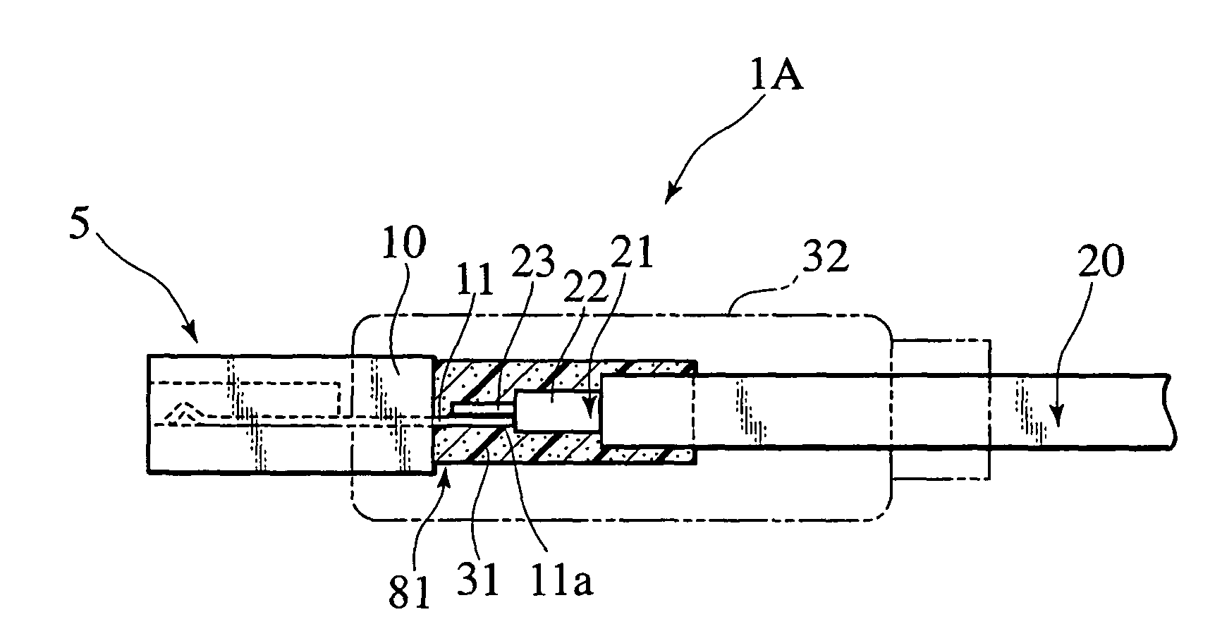
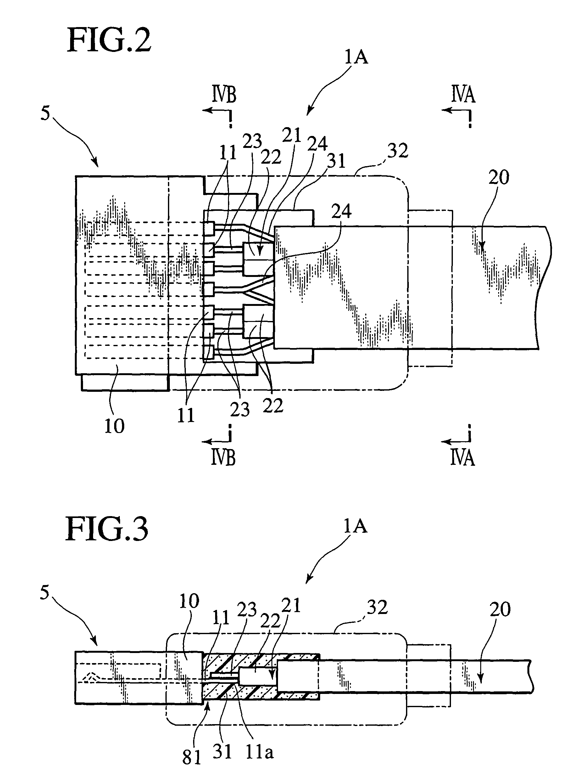
[0010]According to the first aspect, the impedance of the connection portions of the conductor and the terminal is controlled with the permittivity of the foam element. The permittivity of the foam element is quantitatively determined by the permittivity of matrix and the foam ratio, allowing the impedance of the connection portion according to the foam ratio of the foam element to be arbitrarily set. Thus, the loss on the connection portions is reduced to provide an electrically stable electrical connector.
[0018]According to the second aspect, the conductor is covered with the foam element by one operation, which provides a mechanically stable product.

Problems solved by technology

Impedance control to a predetermined value is difficult, such as matching of the impedance of the connection portion to the impedance of the insulation covered portion.

Method used


Image

  • Electric connector and cable
  • Electric connector and cable
  • Electric connector and cable

Examples


second embodiment

[0076]Referring to FIG. 9 and FIG. 10, a cable 1B of a second embodiment is described. Hereunder, members and parts corresponding to FIG. 2 and FIG. 3 are designated by the identical reference numerals and codes, and the description is omitted.

[0077]An electrical connector 5 includes a pair of covering parts 33A and 33B separated into halves. The parts 33A and 33B are formed in such shapes in advance so as to conform to the shape of a connection portion 81 between a connection terminal 11 and the end of a conductor 23, as well as the connection portion between an earth terminal 11 and the end of a drain wire 24. The covering parts 33A and 33B are covered and fitted to the whole of respective connection portions 81.

[0078]In this embodiment, setting of the foam ratio of the foam resin constituting the covering part half bodies 33A and 33B controls the impedance of the electrical connector 5 to an appropriate predetermined value. This embodiment optimizes the impedance of the electrica...

third embodiment

[0079]Referring to FIG. 11 and FIG. 12, a cable 1C of a third embodiment is described.

[0080]On an electrical connector 5, a foam resin tape 34 is wound and fitted around a connection portion 81 between a connection terminal 11 and the end of a conductor 23, as well as a connection portion between an earth terminal 11 and an end of a drain wire 24. The entire connection portion 81 is covered with foam resin tape 34.

[0081]In this embodiment, setting of the foam ratio of the foam resin constituting the foam resin tape 34 appropriately controls the impedance of the electrical connector 5 to a predetermined value. This embodiment optimizes the impedance of the electrical connector 5 according to requirements similarly to embodiment 1.

fourth embodiment

[0082]Referring to FIG. 13, a cable 1D of a fourth embodiment is described.

[0083]An electrical connector 1D includes an insulation covered electric wire 40, comprising a conductor 41 covered with an insulator 42. The conductor 42 at the end portion of the covered electric wire 40 is removed to expose a conductor 41. The end of the exposed conductor 41 has a solderless terminal 51 crimped thereto. Together with the solderless terminal 51, the end of the covered electric wire 40 is inserted into and fitted in a connector housing 60.

[0084]The connection portion between the end of the conductor 41 of the covered electric wire 40 and the solderless terminal (connection terminal) 51 is housed within the connector housing 60. The connector housing 60 is made from a foam resin in which the foam ratio has been adjusted.

[0085]Thus, in this embodiment, setting of the foam ratio of the foam resin constituting the connector housing 60 appropriately controls the impedance of the electrical connec...


PUM


Abstract

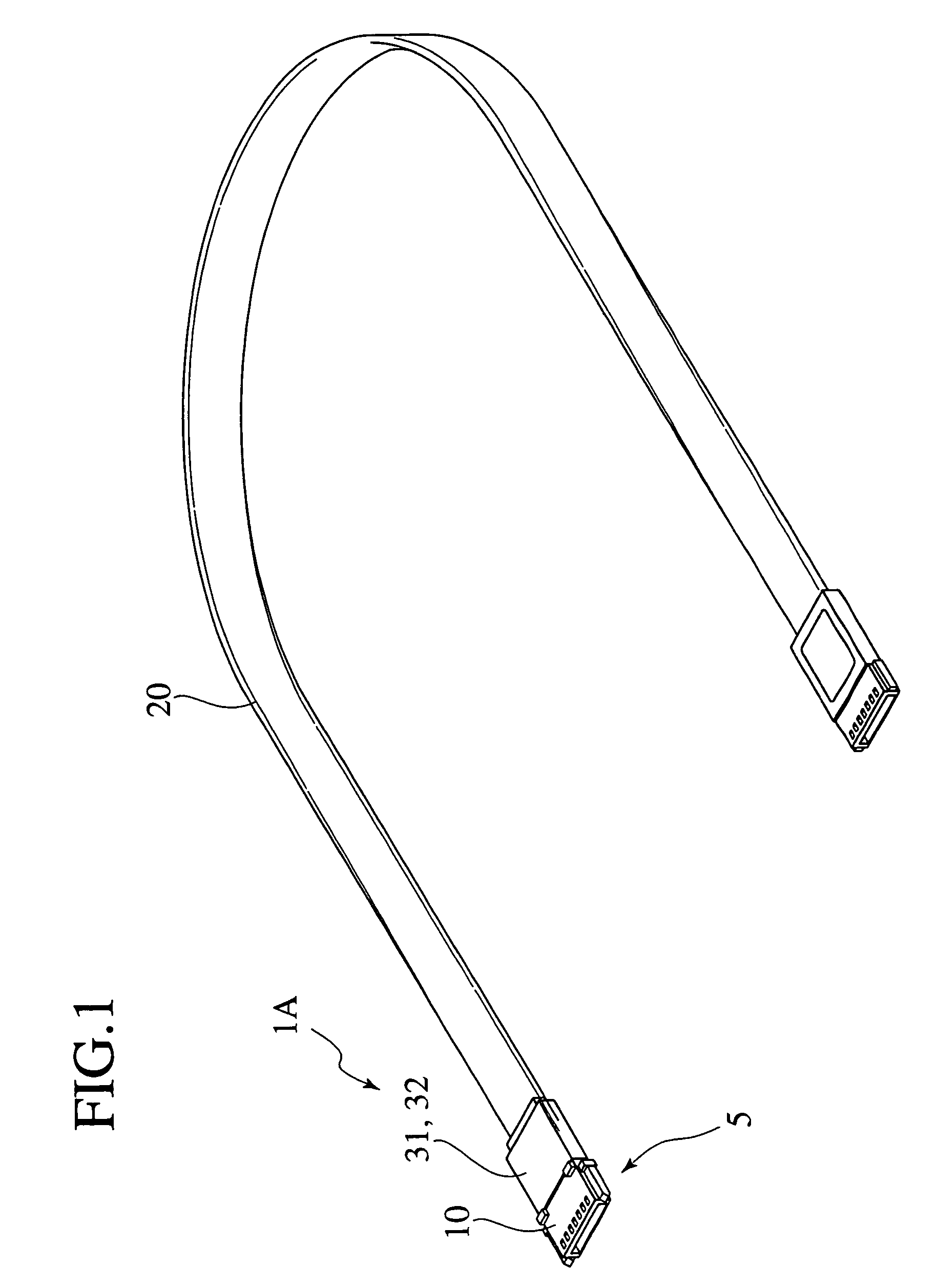
An electrical connector includes a terminal (11) fixed to a connector housing (10). The electrical connector includes a conductor (23) exposed from a covering (22) and having a connection portion connected to a connection portion of the terminal (11). The electrical connector includes a foam element (31) at a predetermined foam ratio located around respective connection portions of the conductor (23) and the terminal (11).

Description

TECHNICAL FIELD[0001]The invention relates to an electrical connector and a cable, and more particularly relates to an electrical connector and a cable for signal transmission having impedance characteristics.BACKGROUND ART[0002]An electrical connector has an insulation covered electric wire having the end of a conductor, from which an insulator was removed. The electrical connector has a connection terminal conducted and connected with this end. The connection portion between the end of the conductor and the connection terminal is protected by a plastic connector housing (plastic cover), a polyvinyl chloride resin (PVC) mold, or the like.[0003]With the conductor covered with the insulator, the impedance of the insulation covered electric wire is determined by the permittivity of the insulator. However, the insulator is removed from the terminal of the insulation covered electric wire, and the conductor is exposed to conduct and connect to the connection terminal of the electrical c...

Claims


Application Information

Patent Timeline
Patent Type & Authority Patents(United States)
IPC IPC(8): H01R4/00H01R13/52H01R13/658H01R13/646H01R13/648H01R43/24
CPCH01R12/592H01R13/5216
Inventor ASHIDA, SHIGERUSHINOHARA, TOMOYUKI
Owner FUJIKURA LTD
Why Eureka
Try Eureka