Methods and apparatus for providing a liquid coating for an organic photoconductive drum

a technology of organic photoconductive drums and liquid coatings, which is applied in the direction of cleaning using liquids, instruments, applications, etc., can solve the problems of affecting the electrical performance the surface layer of the organic photoconductive drum is often damaged, and the remanufactured organic photoconductive drum is often unusable, so as to save the cost of purchasing and improve the electrical performance.

Inactive Publication Date: 2011-07-26
STATIC CONTROL COMPONENTS INC
View PDF4 Cites 0 Cited by
  • Summary
  • Abstract
  • Description
  • Claims
  • Application Information

AI Technical Summary

Benefits of technology

[0009]In order to coat the used organic photoconductive drum the surface of the organic photoconductive drum must first be cleaned. The surface may be cleaned simply by blowing off the existing toner, paper dust or worn surface particles. Preferably dry compressed filtered air is used to blow off any particles on the surface. More preferably still, a cloth containing a dielectric non-polar liquid with a viscosity of less than 200 CentiStokes (cSt) and a surface energy of less than the surface energy of the surface of the used organic photoconductive drum is used to remove the toner and any other particles from the surface of the used organic photoconductive drum. This method is preferred because it combines the cleaning of the surface of the used organic photoconductive drum with the coating of the surface of the used organic photoconductive drum described next. The cleaned organic photoconductive drum is then coated with a dielectric non-polar liquid with a viscosity of less than 200 Centistokes measured at 40 degrees Celsius. The dielectric non-polar liquid has a surface energy less than that of the surface of the used organic photoconductive drum. This difference in surface energy allows the dielectric non-polar liquid to penetrate any gouges, pores or irregularities in the surface of the used organic photoconductive drum. The difference in surface energy also means that the dielectric non-polar liquid will adhere to surface of the used organic photoconductive drum. The dielectric non-polar liquid may be applied in any number of ways, including soaking a cloth in the liquid and rubbing the cloth against the surface of the used organic photoconductive drum. After the surface of the used organic photoconductive drum is coated with a layer of dielectric non-polar liquid, any excess dielectric non-polar liquid may be removed, preferably with a dry lint free cloth leaving a thin layer of the dielectric non-polar liquid on the surface of the used organic photoconductive drum. In the preferred embodiment, the dielectric non-polar liquid is given time to penetrate any pores gouges cracks or crevices in the surface of the used organic photoconductive drum before any excess dielectric non-polar liquid is removed. The resulting surface layer provides better electrical characteristics to the used organic photoconductive drum, and provides a durable wear layer that remains with the used organic photoconductive drum during the reuse of the used organic photoconductive drum. A used organic photoconductive drum with a dielectric liquid surface layer allows remanufacturers and other entities that repair electro photographic devices to save the expense of purchasing a new organic photoconductive drum when remanufacturing laser toner or drum cartridges.

Problems solved by technology

It is obviously more expensive for a remanufacturer to replace an organic photoconductive drum than it is to reuse the old one.
However, used organic photoconductive drums are often unusable.
As a result a used organic photoconductive drum often exhibits gouges, cracks or crazing in the surface layer of the organic photoconductive drum.
These wear defects may show up as print defects if the drum is reused.
Even if the wear defects are not visible many remanufacturers are unwilling to take the risk of re-using a used organic photoconductive drum because the wear defects could appear in the middle of the next cycle of the organic photoconductive drum.
There are two difficulties with this product.
First, it does not work well as the lubricating material appears to be cleaned off of the drum during the second cycle by the wiper blade.
Second, powdered PTFE is a hazardous material, which if inhaled can cause flu like symptoms.
While the mica based Methuselah power is non-hazardous, and is lubricious, it does not restore the electrical characteristics of the used photoconductive drum.
These recoating resins do not perform well in a remanufacturing setting.
They protect the surface of the used organic photoconductive drum from additional wear, but are difficult to evenly apply frequently putting the organic photoconductive drum slightly out of round due to sag in the resin during the cure.
In addition, these resin coatings are typically too resistive, and change the electrical characteristics of the used organic photoconductive drum in unfavorable ways.

Method used


Image

  • Methods and apparatus for providing a liquid coating for an organic photoconductive drum
  • Methods and apparatus for providing a liquid coating for an organic photoconductive drum
  • Methods and apparatus for providing a liquid coating for an organic photoconductive drum

Examples


Embodiment Construction

[0022]New organic photoconductive drums may be sold by original equipment manufacturers (OEMs) in a frame or cartridge containing many other components including toner, developer rollers, primary charge rollers and the like, or they may be sold separately either by an OEM (as is more common in the copier industry) or by an aftermarket organic photoconductive drum manufacturer as a replacement part for an OEM organic photoconductive drum.

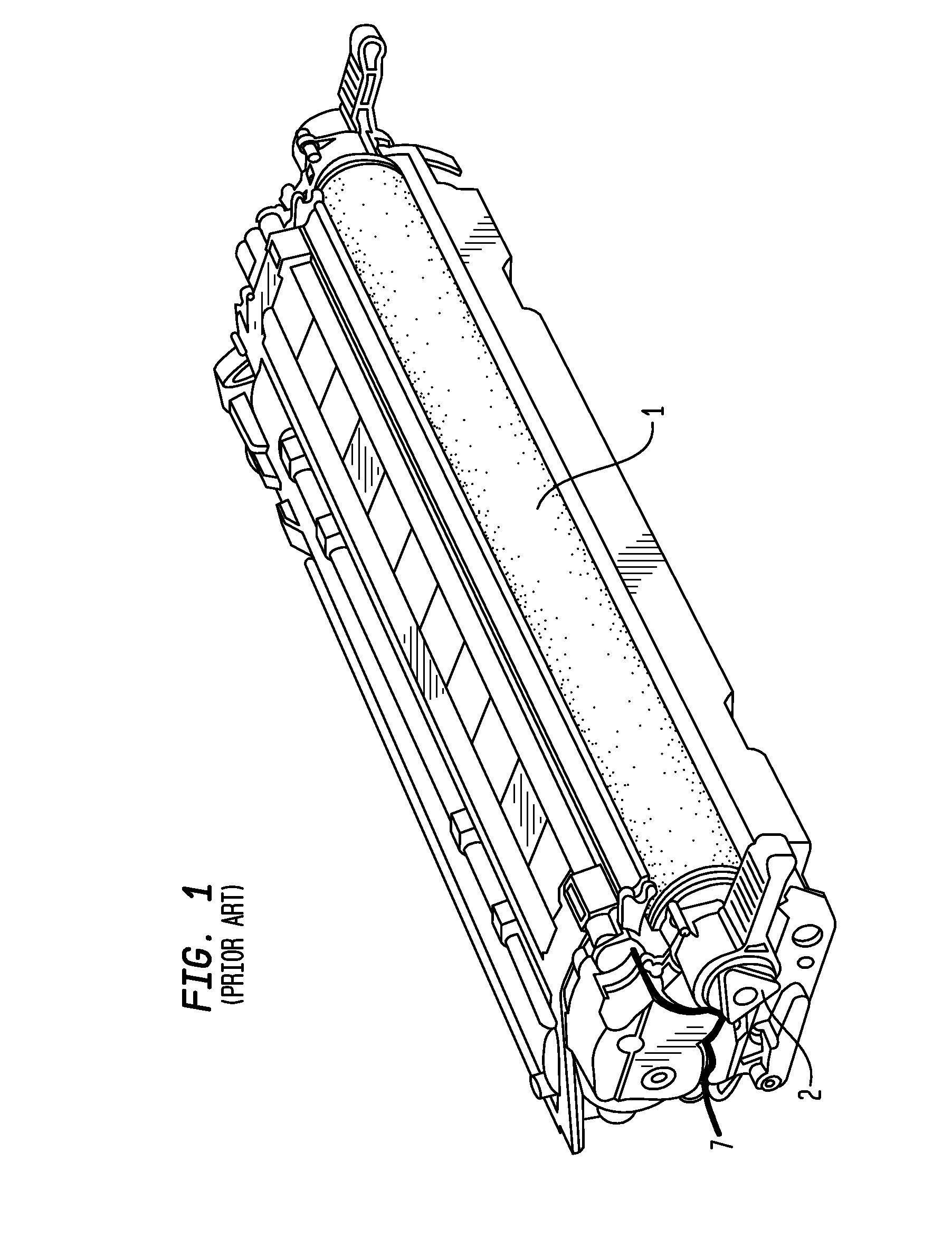
[0023]The prior art contains a number of different cartridge arrangements that may be used by OEMs. One such arrangement is illustrated in FIG. 1. FIG. 1 shows a Hewlett Packard 2600 toner cartridge. This toner cartridge has an organic photoconductive drum 1, and the organic photoconductive drum has a drive gear 2 attached to one end. The toner cartridge of FIG. 1 has two sections, a toner hopper section and a waste bin section. These sections join at the match line 7 shown in FIG. 1. A typical toner hopper section, also from a Hewlett Packard 2600 c...


PUM


Abstract

A method of cleaning and coating a used organic photoconductive drum is disclosed. Using this method remanufacturers can reliably reuse certain used organic photoconductive drums which could not be reused without this method. The method comprises providing a used organic photoconductive drum, cleaning the surface of the used organic photoconductive drum, applying a new surface layer comprising a non-volatile non-polar dielectric fluid such as a silicone oil with a viscosity of less than 200 cSt at 40 degrees Celsius. The resulting liquid surface on the used organic photoconductive drum provides wear resistance, and improved electrical characteristics allowing the used organic photoconductive drum to be used at least a second time.

Description

[0001]The present application is a continuation of allowed U.S. patent application Ser. No. 11 / 977,364 filed Oct. 23, 2007, now U.S. Pat. No. 7,588,873 which is incorporated by reference herein in its entirety.BACKGROUND[0002]A number of different companies manufacture imaging devices such as copiers, printers, fax machines, or all in one devices that perform all of these functions. These imaging devices typically use light to illuminate a light sensitive drum which is coated with a material that causes the illuminated area to differentially charge when compared to the un-illuminated areas of the drum. This differential charge forms a latent image on the cylinder or drum. Toner is attracted to this latent image on the surface of the drum, and then is transferred through well known processes to some media such as paper.[0003]The light sensitive drum originally was a selenium coated drum. For cost and environmental reasons the selenium coating has been replaced with a variety of organ...

Claims


Application Information

Patent Timeline
Patent Type & Authority Patents(United States)
IPC IPC(8): B05C13/02
CPCG03G15/752G03G21/0005G03G21/0094G03G2221/1606
Inventor SWARTZ, EDWIN H.BOONE, RODERICK CRAIGPICKETT, JOHN EDWARDLEWIS, LAWRENCE DALE
Owner STATIC CONTROL COMPONENTS INC
Why Eureka
Try Eureka