Surface acoustic wave element

a surface acoustic wave and element technology, applied in piezoelectric/electrostrictive/magnetostrictive devices, piezoelectric/electrostriction/magnetostriction machines, electrical apparatus, etc., can solve the problems of reducing the characteristics of the saw element, increasing the manufacturing cost, and reducing the operating frequency. , to achieve the effect of reducing the influence of the electrode pair on the surface acoustic waves, increasing the operating frequency

Active Publication Date: 2010-02-18
SEIKO EPSON CORP
View PDF9 Cites 21 Cited by
  • Summary
  • Abstract
  • Description
  • Claims
  • Application Information

AI Technical Summary

Benefits of technology

[0013]An advantage of the invention is to provide a SAW element that is allowed to increase the operating frequency and has good weather resistance and electrical characteristics.
[0014]A surface acoustic wave element according to a first aspect of the invention includes: a diamond layer; an alumina nitride layer provided on the diamond layer; a silicon oxide layer provided on the alumina nitride layer; and a pair of electrodes provided between the alumina nitride layer and the silicon oxide layer, the electrodes applying a voltage to the alumina nitride layer. If a thickness of the alumina nitride layer is represented by H1, a thickness of the silicon oxide layer is represented by H2, a wavelength of a surface acoustic wave is represented by λ, x is defined as x=2πH1 / λ, and y is defined as y=2πH2 / λ, (x, y) meets all of the following formulas 1 to 4. That is, the formula 1 is y≦0.750×x+0.325; the formula 2 is y≦−0.300×x+1.690; the formula 3 is y≧−0.500×x+0.950; and the formula 4 is y≧0.700×x−0.610.
[0015]By adopting the above-mentioned configuration, a distortion occurs in a portion of the alumina nitride layer (piezoelectric material layer) to which a voltage has been applied by the pair of electrodes. This distortion generates surface acoustic waves. The reflection coefficient of surface acoustic waves on the interface between the alumina nitride layer and the pair of electrodes is lower than the reflection coefficient of surface acoustic waves on the interface between a piezoelectric material layer, which is made of zinc oxide, and the pair of electrodes. Thus, the influence of the pair of electrodes upon the surface acoustic waves is reduced. Therefore, even if the thickness of the electrodes is not reduced, the reflection coefficient is reduced and thus surface acoustic waves are efficiently generated. As a result, the SAW element shows good electrical characteristics.
[0016]Also, while the diamond layer and alumina nitride layer soften due to a temperature increase, the silicon oxide layer hardens due to a temperature increase. The existence of the silicon oxide layer reduces characteristic variations of the whole surface acoustic wave element due to temperature variations.
[0017]As seen, since the surface acoustic wave element has a three-layer structure including the diamond layer, alumina nitride layer, and silicon oxide layer, the surface acoustic wave element shows good characteristics. For the surface acoustic wave element having such a structure, the electromechanical coupling coefficient, the phase velocity of surface acoustic waves, and the temperature dependencies of the electromechanical coupling coefficient and phase velocity depend on the thicknesses of the layers. For the diamond layer, if the thickness thereof is equal to or larger than a range over which the diamond layer vibrates in the thickness direction due to propagation of surface acoustic waves, the thickness does not have much influence on the characteristics of the surface acoustic wave element. On the other hand, for the alumina nitride layer and silicon oxide layer, if thicknesses thereof are changed, the characteristics of the surface acoustic wave element are significantly changed. However, it is unknown to what values the thicknesses of these layers should be set in order to set the electromechanical coupling coefficient, the phase velocity of surface acoustic waves, the temperature dependencies thereof, and the like to desired values. This makes it difficult to obtain a surface acoustic wave element having desired characteristics.
[0018]The inventors improved and developed a numerical model based on the finite element method (FEM) and then performed a numerical simulation while changing the thicknesses of the alumina nitride layer and silicon oxide layer. Also, the inventors evaluated the accuracy of the numerical simulation by conducting a comparative experiment and then confirmed that the accuracy of the simulation was sufficient. As for the phase velocity of SAWs, the difference between the experimental values and calculated values was several percent or less. This will be described in a working example 2 later. From the results of this numeral value simulation, the inventors found that the following extremely good characteristics were able to be obtained by setting the thickness H1 of the aluminum layer and the thickness H2 of the silicon oxide layer within a range meeting all of the above-mentioned the formulas 1 to 4.

Problems solved by technology

This will increase the manufacturing cost.
However, even if the technology disclosed in Japanese Patent No. 3205976 is used, characteristics other than the operating frequency may not be enhanced.
If the reflection coefficient is increased, losses of surface acoustic waves are increased, resulting in reductions in the characteristics of the SAW element.
However, the interdigital transducers increase resistance thereof thereby degrading the electrical characteristics of the SAW element.
Therefore, much effort must be expended to design a SAW element having desired characteristics.
In particular, while the characteristics of the SAW element are stabilized against temperature variations by providing a temperature compensation layer as described in Japanese Patent No. 3205976, an increase in the number of components makes it more difficult to design a SAW element.
This makes it difficult to obtain a SAW element having desired characteristics.
In other words, the characteristics of a SAW element cannot be enhanced.
This distortion generates surface acoustic waves.
This makes it difficult to obtain a surface acoustic wave element having desired characteristics.

Method used


Image

  • Surface acoustic wave element
  • Surface acoustic wave element
  • Surface acoustic wave element

Examples


working example 1

[0079]Next, a manufacturing method and characteristics of a SAW element according to a working example 1 will be described. FIG. 6A is a schematic plan view showing an outline configuration of a SAW element 200 according to this working example and FIG. 5B is a sectional view as seen from the direction of lines C-C′. While the SAW element 200 is different from the SAW element 100 according to the first embodiment in that the SAW element 200 is one-port resonator, the SAW element 200 has the same sectional structure as that of the SAW element 100.

[0080]As shown in FIGS. 5A and 5B, the SAW element 200 includes an aluminum nitride layer 230 and a silicon oxide layer 240 provided on the aluminum nitride layer 230. An IDT 250 and a reflector 270 are provided between the aluminum nitride layer 230 and silicon oxide layer 240. The IDT 250 includes a pair of interdigital transducers 251 and 252. The interdigital transducer 251 includes a trunk 251a and multiple branches 251b and the interdi...

working example 2

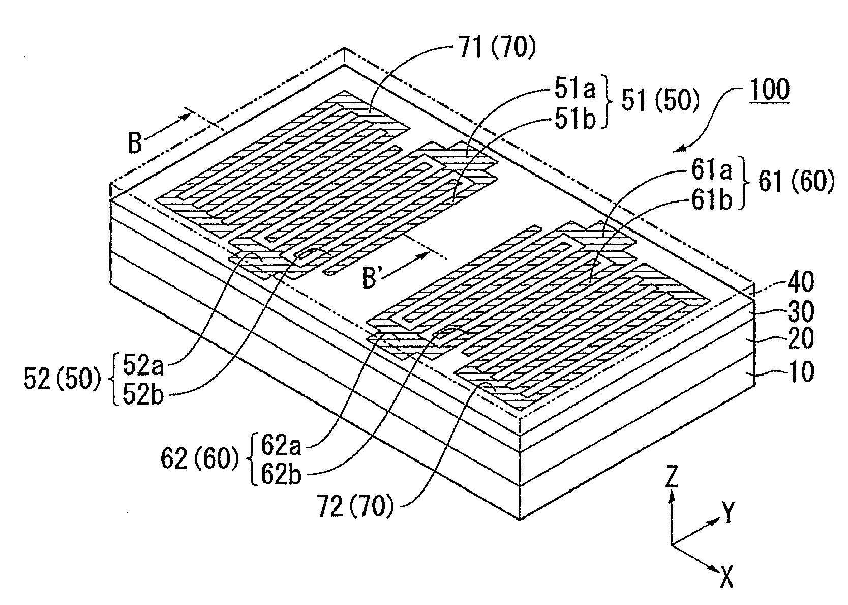
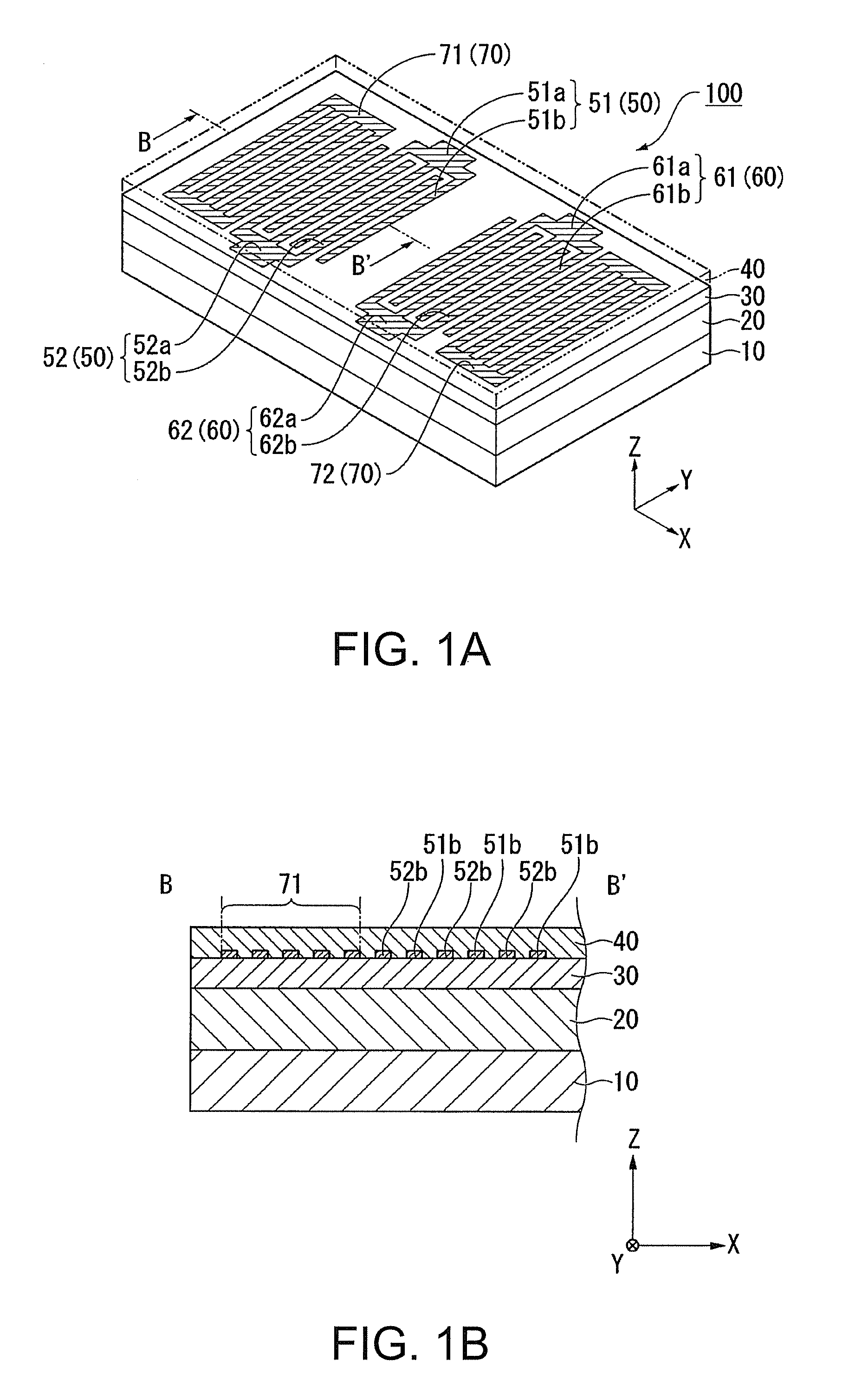
[0093]Next, characteristics of a SAW element according to a working example 2 will be described. The SAW element according to the working example 2 is two-port SAW filter and has the same configuration as that of the SAW element 100 shown in FIG. 1. While the SAW element according to the working example 2 is manufactured using the same manufacturing method as that of the working example 1, the working example 2 is different from the working example 1 in sizes of components and the like. For the SAW element according to the working example 2, the wavelength λ of SAWs was 1.6 μm, a value x (x=2πH1 / λ) obtained by non-dimensionalizing the thickness H1 of the alumina nitride layer was 3.06, and a value y (y=2πH2 / λ) obtained by non-dimensionalizing the thickness H2 of the silicon oxide layer was 3.14. That is, for the working example 2, the values of (x, y) were selected from the area A3.

[0094]Also, a value Z (Z=2πH2 / λ) obtained by non-dimensionalizing the thickness H3 of the IDT was 0.26...


PUM


Abstract

A surface acoustic wave element includes: a diamond layer; an alumina nitride layer provided on the diamond layer; a silicon oxide layer provided on the alumina nitride layer; and a pair of electrodes provided between the alumina nitride layer and the silicon oxide layer, the electrodes applying a voltage to the alumina nitride layer. If a thickness of the alumina nitride layer is represented by H1, a thickness of the silicon oxide layer is represented by H2, a wavelength of a surface acoustic wave is represented by λ, x is defined as x=2πH1/λ, and y is defined as y=2πH2/λ, (x, y) meets all of the following formulas 1 to 4 below. That is, the formula 1 is y≦0.750×x+0.325; the formula 2 is y≦−0.300×x+1.690; the formula 3 is y≧−0.500×x+0.950; and the formula 4 is y≧0.700×x−0.610.

Description

CROSS-REFERENCE TO RELATED APPLICATION[0001]This application is based on and claims priority from Japanese Patent Application No. 2008-208585, filed on Aug. 13, 2008, the contents of which are incorporated herein by reference.BACKGROUND[0002]1. Technical Field[0003]The present invention relates to a surface acoustic wave element.[0004]2. Description of the Related Art[0005]A surface acoustic wave element has been used as a filter, a resonator, or the like in an electric communication apparatus such as a cell phone. A surface acoustic wave element is an electromechanical conversion element using surface acoustic waves (hereafter referred to as “SAWs”) that propagate over a surface of an elastic body (for example, see Japanese Patent No. 3205976).[0006]A SAW element disclosed in Japanese Patent No. 3205976 includes a hard layer made of diamond, a ZnO layer (piezoelectric material layer) formed on the hard layer, a silicon dioxide layer (temperature compensation layer) formed on the Zn...

Claims


Application Information

Patent Timeline
Patent Type & Authority Applications(United States)
IPC IPC(8): H01L41/00H03H9/145H03H9/25
CPCH03H9/14538H03H9/02574
Inventor UMEDA, TAKATOSHIKAWANO, SHUICHIFUJII, SATOSHI
Owner SEIKO EPSON CORP
Why Eureka
Try Eureka