Socket assembly for card

a socket and card technology, applied in the field of socket assembly for cards, can solve the problems of short transmission paths of the connection portions of the socket and the small socket assembly, and achieve the effect of facilitating positioning

Inactive Publication Date: 2006-11-09
HIROSE ELECTRIC GROUP
View PDF7 Cites 0 Cited by
  • Summary
  • Abstract
  • Description
  • Claims
  • Application Information

AI Technical Summary

Benefits of technology

[0009] Therefore, an object of the present invention is to provide a socket assembly for cards, having a smaller size and better electrical characteristics.
[0014] The housing has a plurality of wall portions extending downwardly, in which the support portions are provided. Separation spaces or air layers are provided between the respective wall portions to reduce the interference in the high-speed transmission.
[0017] By providing shield plates between the respective support portions of the connector, it is possible to produce the shield effect between the connection portions of the terminals.
[0018] By linking wall portions of the connector to each other with side wall portions provided at side ends of the wall portions in a terminal arrangement direction, it is possible to reinforce the wall portions.
[0019] Providing the connector with engagement posts extending downwardly to be plugged into engagement dents provided in a connector attached to a circuit board facilitates the positioning between the socket assembly and the circuit board upon plugging operation.
[0020] As described above, since the sockets are piled one upon another on the circuit board in the order of length, from small to large, of the sockets in the card insertion direction, the connection portions of the terminals can be arranged in the stepped region provided by the rear portions of the sockets due to the difference in length of the sockets. Consequently, the socket assembly can be made small in the card insertion direction and the length of the connection portion of the terminal of the upper socket can be minimized, which results in the improvement of electrical characteristics in the high-speed transmission.

Problems solved by technology

Consequently, the socket assembly becomes small in the card insertion direction and the transmission paths of the connection portions of the terminals become also short.

Method used


Image

  • Socket assembly for card
  • Socket assembly for card
  • Socket assembly for card

Examples


first embodiment

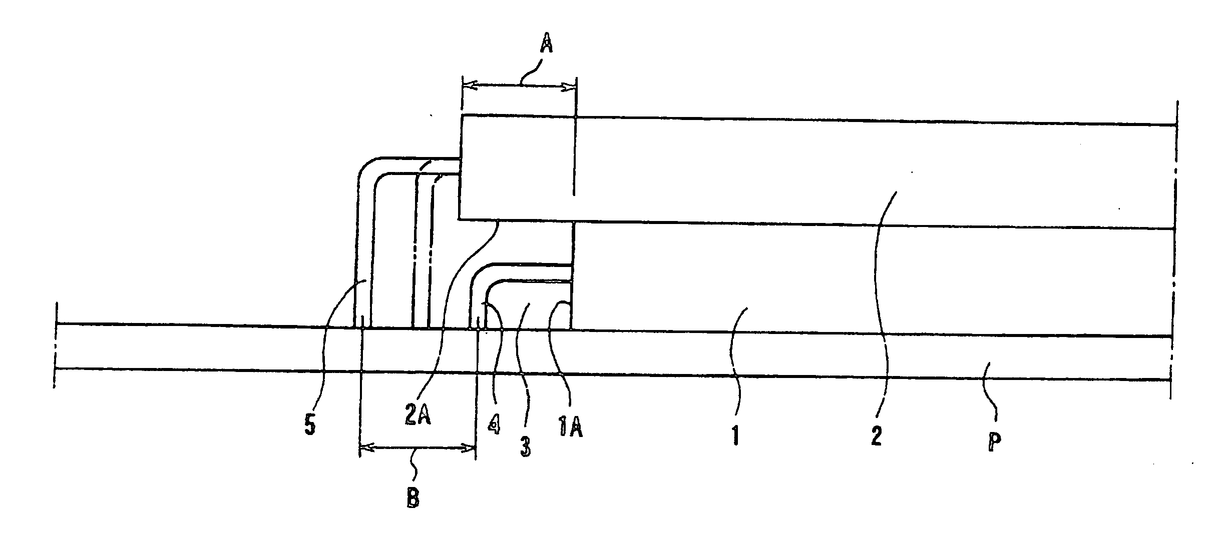
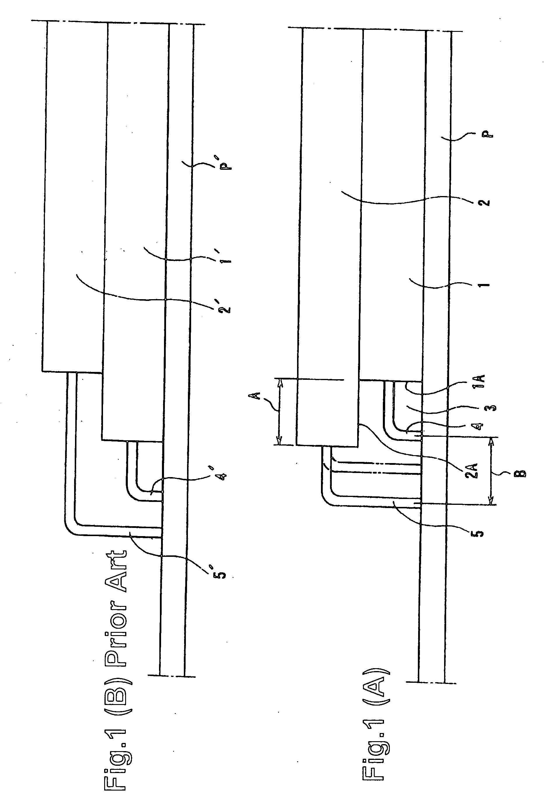
[0030]FIG. 1(A) shows a socket assembly according to the present invention and FIG. 1(B) shows a conventional socket assembly. Each assembly has two sockets having different lengths in the card insertion direction (lateral direction in the drawings). The two sockets are piled in two tiers on a circuit board. The respective sockets have openings, into which cards are inserted, on the right-hand side in the drawings. However, the openings are not shown and only the rear ends of the sockets on the left-hand side are shown in the drawings.

[0031] In FIG. 1(A), the socket assembly according to the present invention, a socket 1 in the lowest tier (hereinafter “lowest socket 1”) provided directly on a circuit board P is short and a socket 2 in the upper tier (hereinafter “upper socket 2”) provided on the lowest socket 1 is longer. The openings of the lower and upper sockets 1 and 2 on the right-hand side are arranged at the same position in the card insertion direction. Accordingly, there ...

second embodiment

[0034] The second embodiment has a more complex structure than the first embodiment of the present invention. In the first embodiment, the connection portions of the terminals of the sockets are directly connected to the circuit board. In the second embodiment, the connection portions are connected to the circuit board through a first connector fixed to the sockets and a second connector fixed to the circuit board.

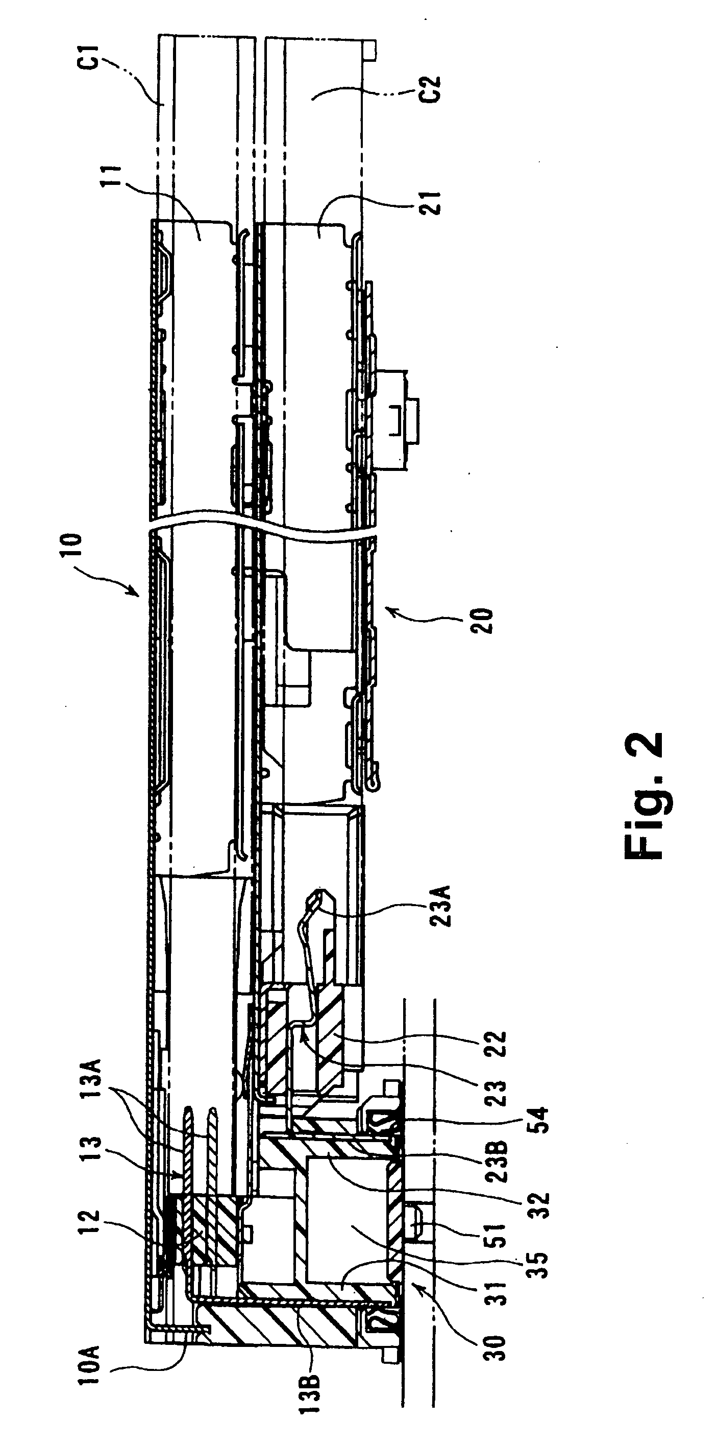
[0035]FIG. 2 is a sectional view of a socket assembly according to the second embodiment, FIG. 3 is a perspective view of main parts, such as sockets and connectors, of the socket assembly of FIG. 2, showing the status after the main parts are separated, and FIG. 4 is a sectional view of the rear side of the main parts of FIG. 3.

[0036] In FIG. 3, the socket assembly comprises a socket 10 provided in an upper tier (hereinafter “upper socket 10”), a socket 20 provided in a lower tier (hereinafter “lower socket 20”), and a socket connector 30. The socket connector 30 is plu...

third embodiment

[0053] In the third embodiment shown in FIG. 7, a shield plate 60 is provided in the connector 30 between the connection portions 13B and 23B of the terminals 13 and 23 of the sockets 10 and 20.

[0054] In FIG. 7(B), a groove 41, which is adapted to receive the shield plate 60 shown in FIG. 7(A), extends vertically at the substantially center of the front wall 32 of the socket 30 in the thicknesswise direction of the front wall portion 32 and is opened forwardly on the upper side thereof.

[0055] In this embodiment, most of the terminals 23 of the socket 20 are used as signal terminals but some of the terminals 23 are used as ground terminals. The shield plate 60 has several resilient contact portions 61 at the upper edge thereof. The contact portions 61 are made by bending the shield plate 60 at positions corresponding to those of the ground terminals. In an example shown in FIG. 7(A), four contact portions 61 are provided corresponding to four ground terminals.

[0056] A plurality of...


PUM


Abstract

A socket assembly comprises a plurality of sockets (1 and 2) piled up in multiple tiers in the order of length of the sockets (1 and 2). Each of the sockets (1 and 2) has an opening (11 and 21), an accommodation space to receive a card (C1 or C2), and a closing member (12). A plurality of terminals are provided in the closing member (12) and have connection portions (4 and 5) on rear sides thereof extending rearwardly into the outside of the accommodation space and bent downwardly at right angles. At least part of the connection portion (4) of the lower-tier socket (1) is accommodated in a stepped space (3) defined by the rear end face of the lower-tier socket (1) and the rear lower face of the upper-tier socket (2).

Description

BACKGROUND OF THE INVENTION [0001] The present invention relates to a socket assembly for cards, especially an assembly having multi-tiered sockets installed on a circuit board in parallel to the surface of the circuit board. [0002] Recently, a PC card in conformity of PCMCIA standard has become widespread. The PC card is detachably installed on an electronic device, such as a personal computer, to enlarge the function of the electronic device. On the other hand, an express card is being developed to meet the recent requirements for high-speed information processing and small-sized devices. The express card is smaller than the PC card, corresponding to high-speed signals. [0003] Considering the above-mentioned situation, where the already diffused card (PC card) and the newly diffused card (express card) are intermixed, it is preferable that a socket for the PC card and a socket for the small express card are integrally piled in a socket assembly. [0004] The socket assembly is insta...

Claims


Application Information

Patent Timeline
Patent Type & Authority Applications(United States)
IPC IPC(8): H01R12/00H01R12/50
CPCH01R12/714H01R23/7073
Inventor SUGITA, NOBUHIRO
Owner HIROSE ELECTRIC GROUP
Why Eureka
Try Eureka