Built-in oven with an improved cooling system

a built-in oven and cooling system technology, which is applied in the field of built-in ovens with improved cooling systems, can solve the problems of scale buildup, complex construction, and increased construction costs, and achieve the effect of reducing the condensation problem

Active Publication Date: 2011-10-18
WHIRLPOOL CORP
View PDF14 Cites 12 Cited by
  • Summary
  • Abstract
  • Description
  • Claims
  • Application Information

AI Technical Summary

Benefits of technology

[0009]The technical solution according to the present invention is an innovative air flow system in which the air exhaust area is substantially above the control panel and in which the inlet area of the cooling air is substantially below the control panel. Any steam or water vapor produced inside the oven cavity, captured by the ventilation system and exiting this area is not impacting the control panel, knobs, and buttons or handles, thus dramatically reducing the condensation issue.

Problems solved by technology

This construction is therefore quite complex and expensive.
Despite the lower content of moisture of the discharge air compared to gas oven, nevertheless this is known to create condensation issue as well, particularly while cooking food with high water content at low temperature cooking cycles or when specific environmental conditions are met.
This is creating potential rust spots, scale build up and, and hot spots for customer.
Moreover the condensation of humidity on electronic components behind the control panel, reached through possible apertures in the panel itself, can create potential risk of malfunction of electronic components of the oven.
The solution of the above US document cannot be easily transferred to an electric built-in oven since it was designed for gas ovens.
Moreover its complexity, cost and the presence of a flow of discharge air below the control panel cannot solve the above mentioned problem of condensation in an electric oven.

Method used


Image

  • Built-in oven with an improved cooling system
  • Built-in oven with an improved cooling system
  • Built-in oven with an improved cooling system

Examples


Embodiment Construction

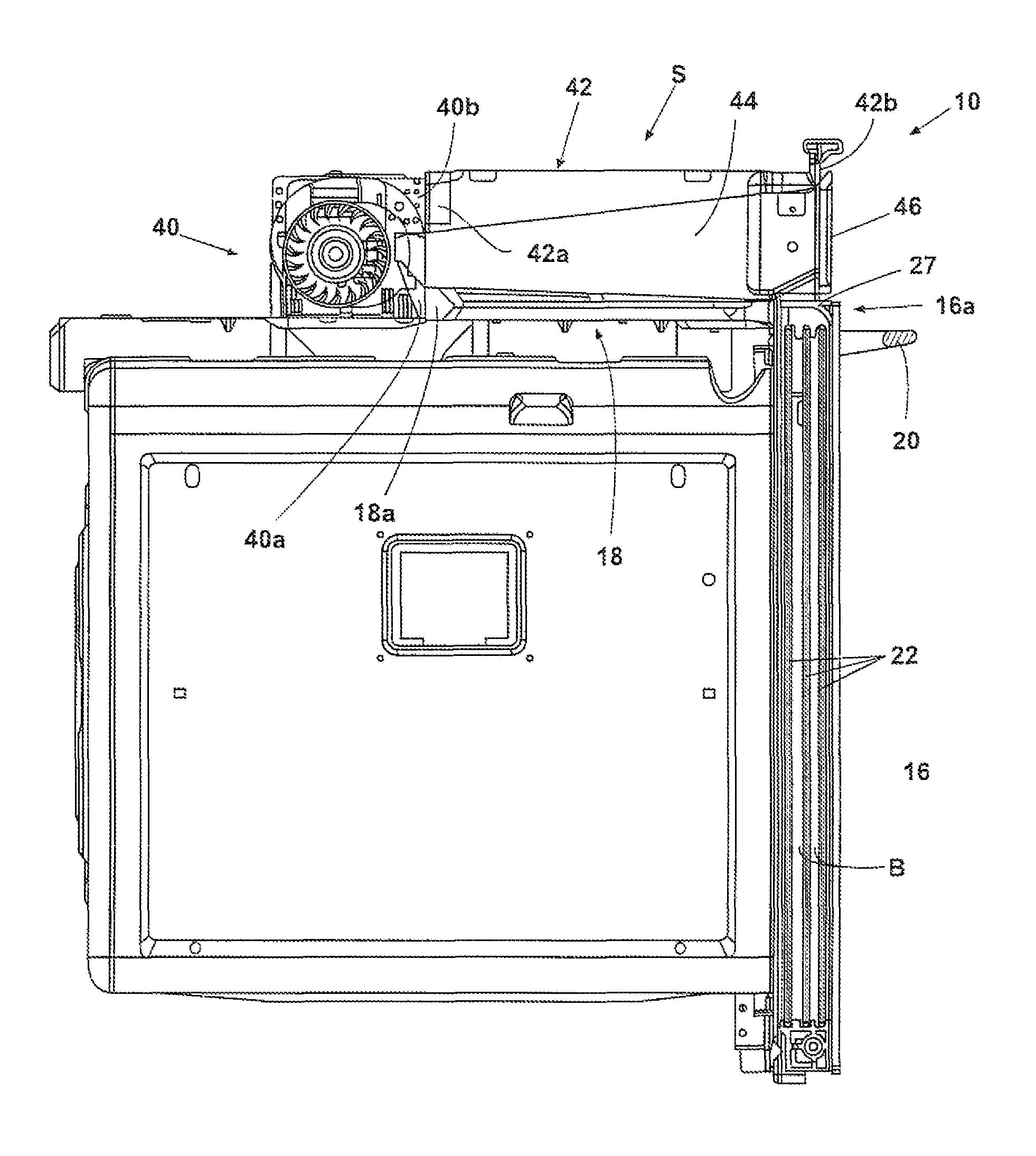
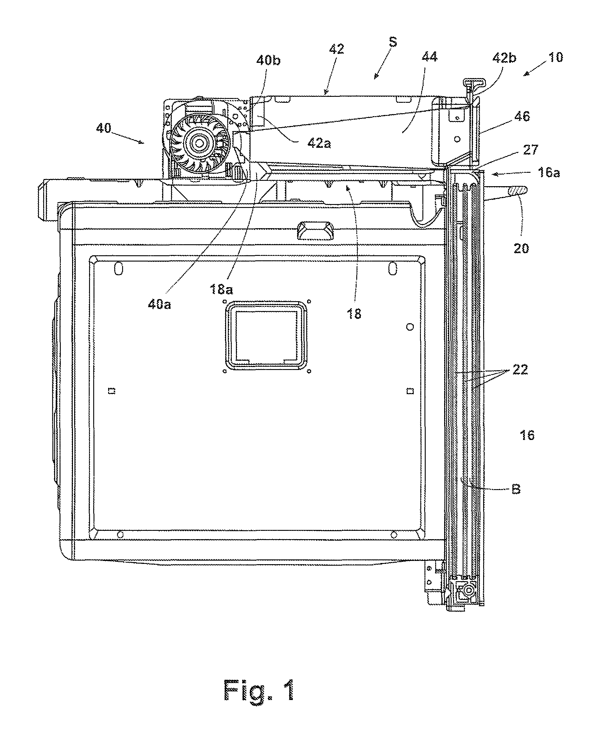
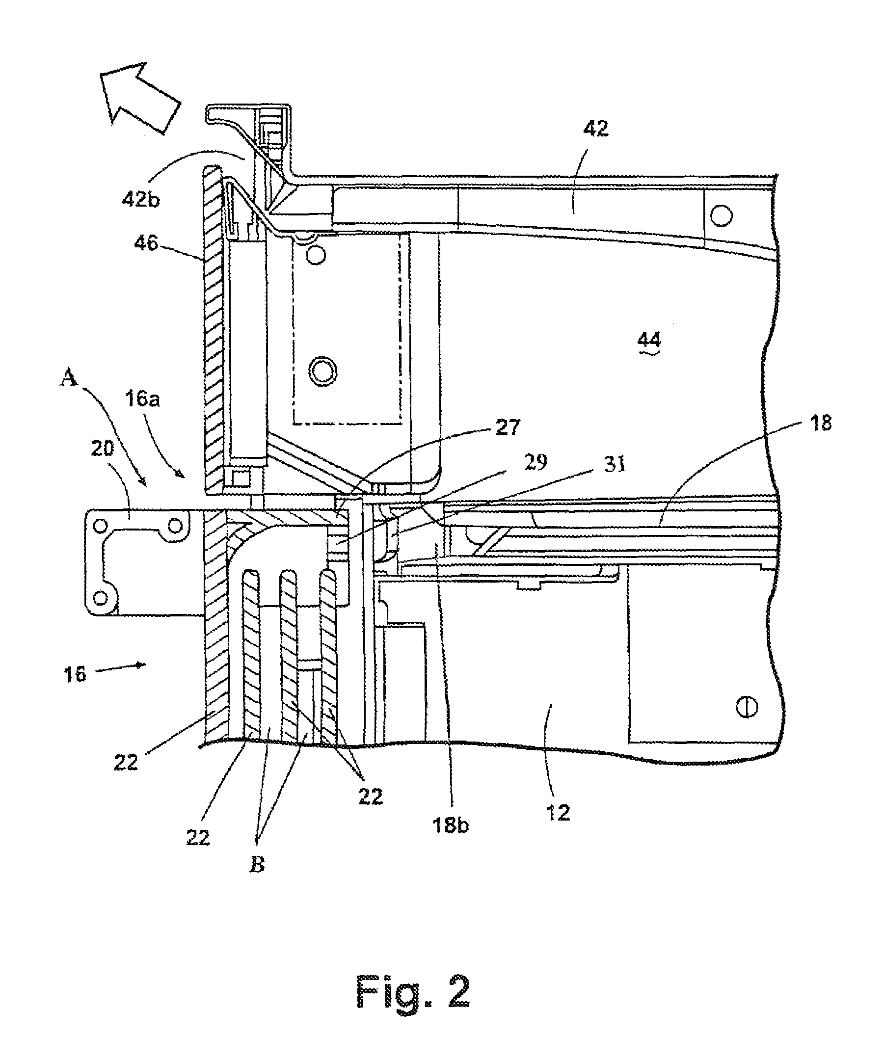
[0014]With reference to the drawings, a built-in oven 10 is shown having a cavity 12 defined by a metal thermally insulated structure 14 closed by a door 16. On top of the metal structure 14 there is defined an air ventilation system having a first lower cooling duct 18, having open ends 18a and 18b, to which is conveyed air around the metal structure of the oven and fresh air A coming from the outside of the oven in the region of an upper edge 16a of the door where a handle 20 is fixed to the door. A certain amount of the air around the metal structure 14 may be conveyed in a known manner through the glass plates 22 of the door 16, in order to cool it. In the embodiment shown in the drawings, the major portion of the cooling air is drawn through an interspace B between the glass plates 22 of the door 16. A deflector 27 is fixed to the upper edge of the door 16 in order to deflect the air flow and to deliver it, through apertures 29, towards an intake opening 31 adjacent end 18b of ...


PUM


Abstract

A built-in oven has a door, a control panel positioned above the door and a cooling system including a fan-motor assembly for drawing cooling air around the outside surface of the oven and an exhaust duct for discharging air to the ambient. The cooling system comprises a cooling air supply duct above the top side of the oven and with an intake opening below the control panel, and an exhaust duct positioned above the supply duct so that its exhaust opening is placed above the control panel, the fan-motor assembly being mounted between the supply duct and the exhaust duct.

Description

BACKGROUND OF THE INVENTION[0001]1. Field of the Invention[0002]The present invention relates to a domestic built-in oven having a door, a control panel positioned above the door and a cooling system including a fan-motor assembly for drawing air around at least a portion of the oven and an exhaust duct for discharging air to the ambient. More specifically the invention is related to the inlet-outlet areas of the ventilation system and the flow path of the air inside the appliance.[0003]2. Description of the Related Art[0004]A built-in oven having an air outlet positioned above the control panel is shown by U.S. Pat. No. 4,865,010. This oven is a gas oven where the problems of vapor condensation on the control panel are quite relevant. Moreover such document discloses also a horizontal cool air duct which has an exhaust opening at the front of the oven, below the control panel and above the door. Even if the air discharged by such cool air duct does not contain the moisture containe...

Claims


Application Information

Patent Timeline
Patent Type & Authority Patents(United States)
IPC IPC(8): A21B3/00A21B3/02F24C15/02F24C15/32
CPCF24C15/006
Inventor VENEZIA, MICHELEGIULIANI, MARCOMAZZETTI, CRISTINA
Owner WHIRLPOOL CORP
Why Eureka
Try Eureka