
Light microscope with novel digital method to achieve super-resolution

Active Publication Date: 2011-10-18
WAVEFRONT ANALYSIS
View PDF10 Cites 2 Cited by
  • Summary
  • Abstract
  • Description
  • Claims
  • Application Information

AI Technical Summary

Benefits of technology

The method consistently and reliably retrieves the phase distribution, achieving phase retrieval with high accuracy, as demonstrated by simulations, and has implications for X-ray crystallography and other applications.

Problems solved by technology

This means that if there are doubtful or missed data points in the diffraction plane, the algorithm will generate the complex values that must be there.

Method used


Image

  • Light microscope with novel digital method to achieve super-resolution
  • Light microscope with novel digital method to achieve super-resolution
  • Light microscope with novel digital method to achieve super-resolution

Examples


Embodiment Construction

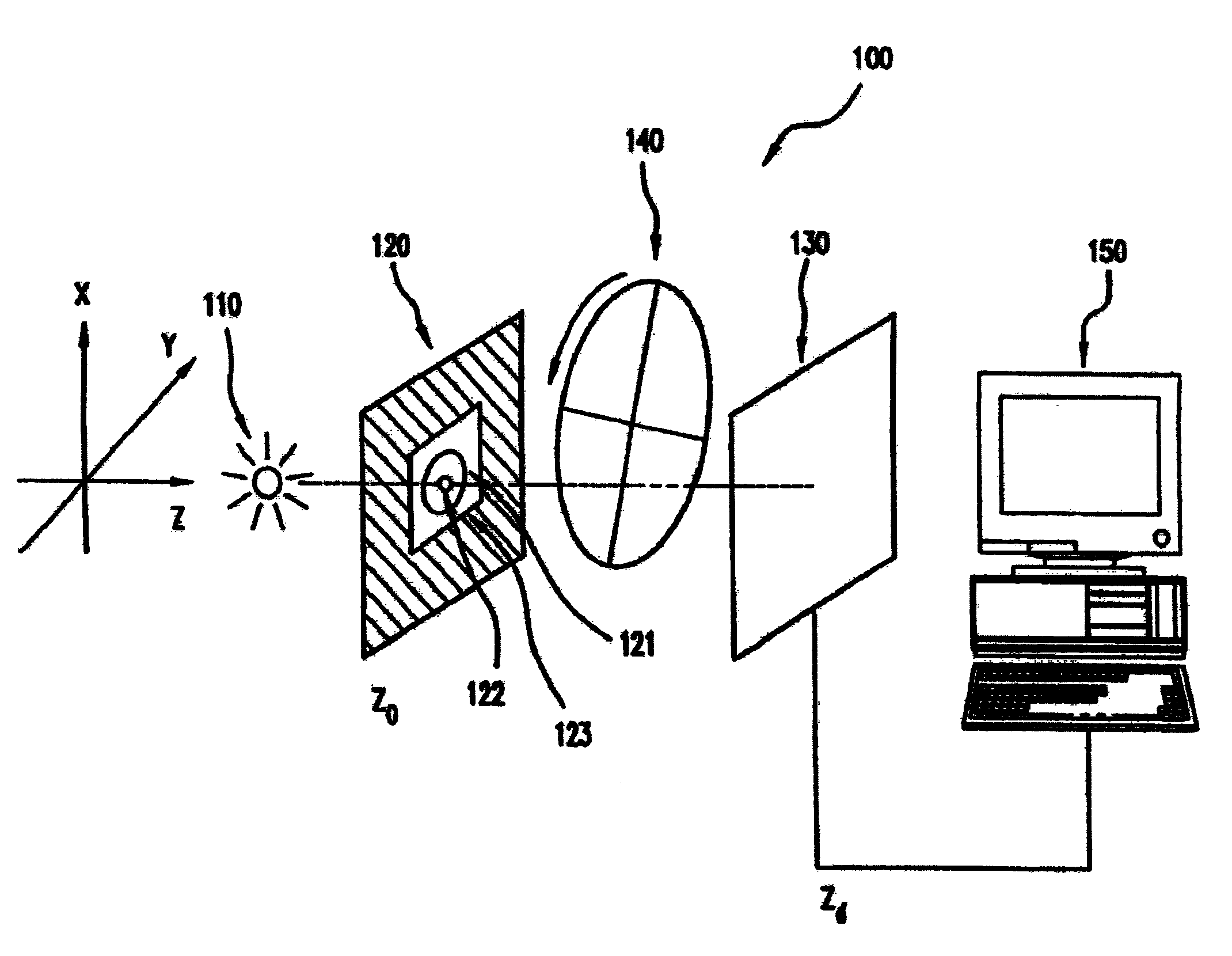
To describe the new algorithm, I begin with the minimum physical essentials for collecting data from a transmission type specimen with a range of illumination absorption and phase change distributed over its extent. This specimen is mounted in a hole in a 2 dimensional occluding plane at Zo which is located a distance Zd upstream of the diffraction plane. The size and location of the hole as well as the distance Zd are known. Illumination of the specimen will be by a coherent, uniform amplitude and phase wave front. Immediately upstream or downstream of the specimen (ideally at the specimen) the wave front phase will be changed by a phase filter so that the wave front at the specimen will be the sum of the unknown specimen amplitude and phase distribution and the known phase filter distribution. The filter phase distribution is known. The filter amplitude distribution is equal to a constant of one. Depending on the problem, there will be several different phase filters that will sub...


PUM


Abstract

Methods and apparatus for reconstructing a wave, including interpolation and extrapolation of the phase and amplitude distributions, with application to imaging apparatus, such as microscopes.

Description

BACKGROUND OF THE INVENTIONThe most simple and therefore the most inclusive description of the method that I have discovered to achieve both phase and amplitude reconstruction along with super resolution is based primarily on three mainstays: the Rayleigh-Sommerfeld scalar wave diffraction equation, the mathematical law of Parseval and the principle of reconstruction through “iterative error reduction” (Gerchberg, R. W. and Saxton, W. O., 1972, Optik, 35, 237).Physically, the problem involves a three dimensional instrument having transverse Cartesian coordinates X & Y and an orthogonal Z coordinate along the direction of propagation of the wave front of the scattered radiation. I define two conjugate transverse planes at Xo, Yo and Xd, Yd. The subscripted o (output) plane is upstream of the subscripted d (diffraction) plane with the scattered wave front propagating from output to diffraction plane along the Z axis. To meet the strict requirements of the scalar diffraction equation, ...

Claims


Application Information

Patent Timeline
Patent Type & Authority Patents(United States)
IPC IPC(8): G02B21/00
CPCG02B27/58G02B21/0008G02B21/00Y10S359/90G03H1/0866G03H2001/0816
Inventor GERCHBERG, RALPH W.GERCHBERG, LEGAL REPRESENTATIVE, LOUISE
Owner WAVEFRONT ANALYSIS
Learn More