
Trench measurement system employing a chromatic confocal height sensor and a microscope

a technology of chromatic confocal and height sensor, which is applied in the direction of instruments, measurement devices, microscopes, etc., can solve the problems that the current metrology technology cannot measure the depth of high aspect ratio trenches with speed and accuracy, and profiling instruments using a stylus or other method of contact cannot accommodate an aspect ratio or lateral dimension, so as to achieve fast mechanical movement

Active Publication Date: 2006-05-25
ONTO INNOVATION INC
View PDF15 Cites 140 Cited by
  • Summary
  • Abstract
  • Description
  • Claims
  • Application Information

AI Technical Summary

Benefits of technology

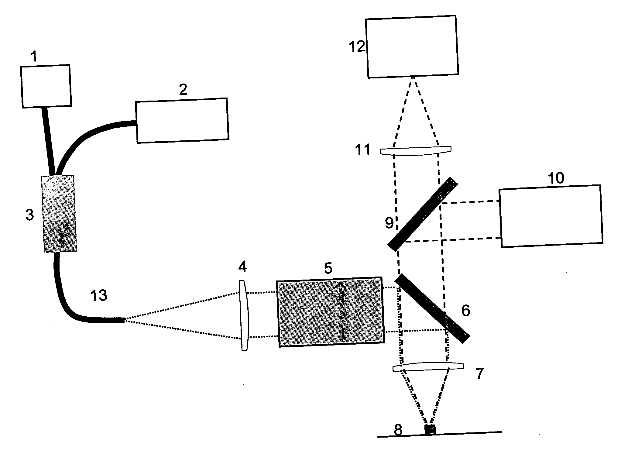
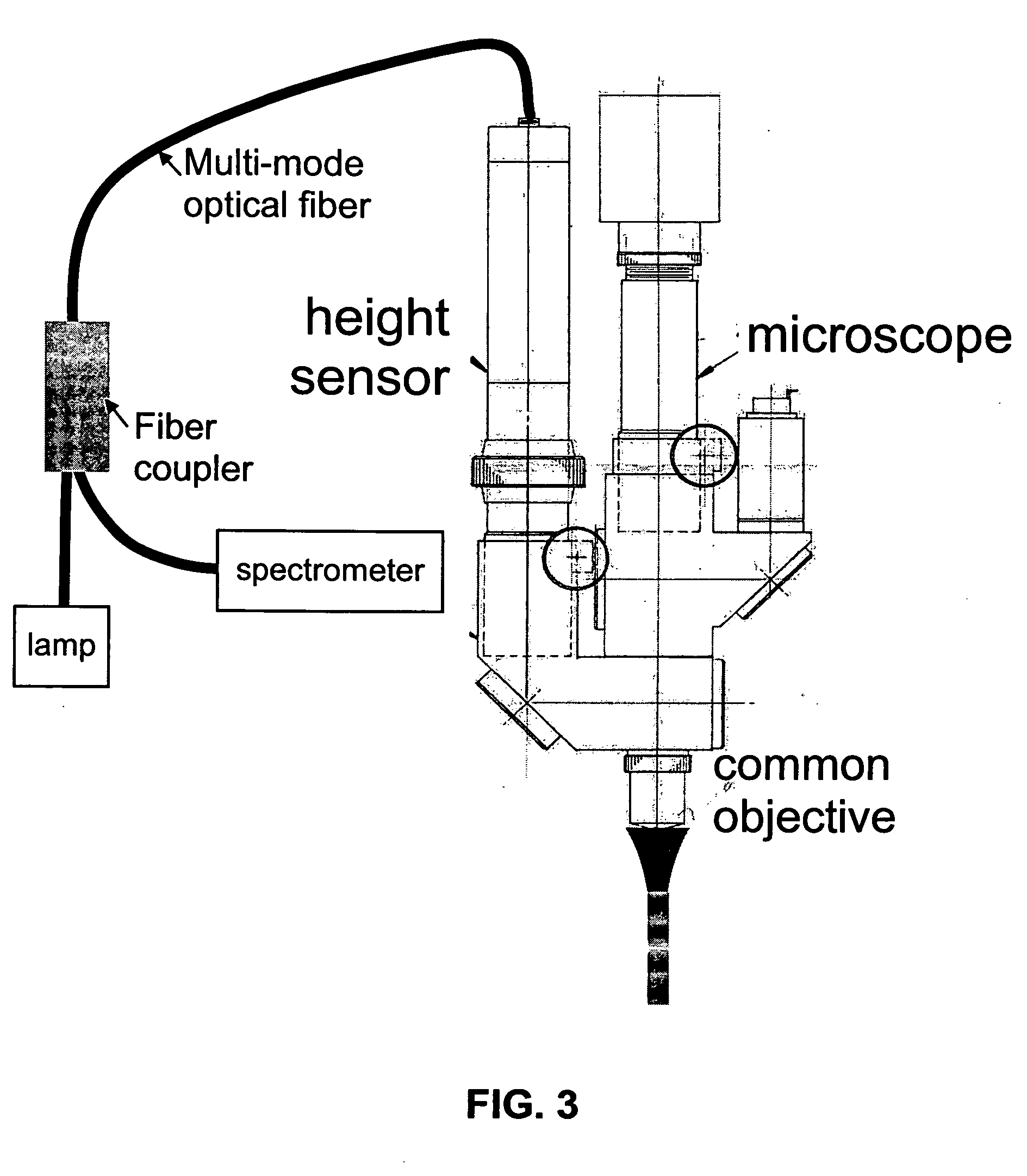
[0013] The present invention combines a traditional imaging microscope with a chromatic confocal, single point, height sensor. This combination instantaneously provides an image of the object and the height value at one point in the image. No mechanical movement is necessary anywhere in the system to achieve that result. However, if height measurements are required in multiple locations, lateral mechanical movement can be used to move the height measuring spot to those locations. Since the image shows precisely the desired lateral locations, the mechanical movements can be fast.

Problems solved by technology

Manufacturers of MEMS devices do not currently have an accurate and inexpensive method to non-destructively measure the depth of etched high aspect ratio trenches.
Current metrology technology cannot measure the depth of high aspect ratio trenches with speed and accuracy.
Because of the very steep sidewalls inherent in such a structure, profiling instruments that use a stylus or other method of contact cannot accommodate an aspect ratio or lateral dimension of this nature.
For example, atomic force microscopes (AFM) and stylus profilers are not suitable because even if the tip could penetrate the trench, it would not be able to follow the side wall, and the tip would break when exiting the trench.
Standard confocal microscopes fail because they confuse the signal from the top of the trench with the signal from the bottom when the trench is too narrow.
Thus, a confusing signal is generated even when the bottom of the trench is far away from the focal plane.
Confocal microscopes are also very slow since they require scanning the measurement sample longitudinally to find the plane of best focus.
White light interferometers have similar difficulties in that they are slow and must scan longitudinally.
In addition, the fringe signal is weak due to the light scattered from the walls and the top.
Phase shift interferometers fail outright because phase unwrapping fails at steep sidewalls.
Finally, triangulation techniques can only succeed if precise control of the direction of the incident beam relative to the direction of the trench is maintained so that the light can get into the trench from the side.
This constraint makes such an instrument unfeasible.
This system has the disadvantage that the microscope objective is used with a short, finite conjugate.
Thus, Molesini's system does not allow simultaneous imaging of the object and height profiling of the object.
In addition, this system is not truly confocal, since it lacks an aperture in an image plane for the reflected light.
Since the single source is spread over the entire field of view, and then spread again in wavelength by the dispersion, these systems require very bright and expensive light sources, such as mercury arc lamps.
Alignment, cost, and complexity are all well-known difficulties with perforated disc type confocal microscopes, which tend to be very expensive.
In addition, the difficulty of fabricating a well-corrected holographic element with large numerical aperture suggests that a small spot size would be difficult to achieve.
None of the above prior art addresses the measurement of a narrow, high aspect ratio trench.

Method used


Image

  • Trench measurement system employing a chromatic confocal height sensor and a microscope
  • Trench measurement system employing a chromatic confocal height sensor and a microscope
  • Trench measurement system employing a chromatic confocal height sensor and a microscope

Examples


Embodiment Construction

[0026] The present invention integrates a simple and inexpensive chromatic confocal height sensor with a simple and inexpensive microscope (FIG. 3). The combination creates a system that measures the height of the object at one location in the microscope's field of view, while simultaneously providing a traditional microscope image indicating exactly the location on the object where the height measurement occurs. In addition, this invention includes a method for using the integrated system to measure the depth of a high aspect ratio trench.

[0027] One object of the present invention is to combine a traditional imaging microscope with a chromatic confocal, single point, height sensor. This combination instantaneously provides an image of the object and the height value at one point in the image. No mechanical movement is necessary anywhere in the system to achieve that result. However, if height measurements are required in multiple locations, lateral mechanical movement can be used ...


PUM


Abstract

A system for the measurement of high aspect ratio trenches. The preferred embodiment consists of three elements: a) an integrated microscope and optical height sensor, b) an axially dispersive, afocal lens system, which is included in the optical height sensor, and c) an algorithm for processing the optical height sensor data to produce the depth of the high aspect ratio trench. The present invention combines a traditional imaging microscope with a chromatic confocal, single point, height sensor. This combination instantaneously provides an image of the object and the height value at one point in the image. No mechanical movement is necessary anywhere in the system to achieve that result. The chromatic confocal height sensor is integrated with a traditional microscope through the use of separate wavelength bands such as a wavelength band in the visible part of the spectrum, and a wavelength band in the infrared or ultraviolet part of the spectrum.

Description

CROSS-REFRENCE TO RELATED APPLICATIONS [0001] This application takes priority from provisional application Ser. No. 60 / 631,226 filed on Nov. 24, 2004.FIELD OF THE INVENTION [0002] The present invention relates generally to an instrument and method for the measurement of high aspect ratio trenches at a micrometer or submicrometer scale. The invention pertains more specifically to a system and related method using in combination a microscope and a chromatic confocal single point optical height sensor. BACKGROUND ART [0003] Many advanced semiconductor fabrication processes involve the construction of high aspect ratio trenches on the micrometer or sub-micrometer scale. For example, micro-electro-mechanical systems (MEMS), which often contain moving parts a few microns wide, are characterized by deep vertical etching processes. The product contains three-dimensional structures with regions of deep, narrow trenches with near-vertical sidewalls. A typical example is a trench etched 5 micr...

Claims


Application Information

Patent Timeline
IPC IPC(8): G01B11/24
CPCG01B11/0608G01B11/24G01B2210/50G02B21/0016G02B21/0064
Inventor MARX, DAVID S.GRANT, DAVID L.
Owner ONTO INNOVATION INC
Learn More