Segmented bar-in-bar target

a target and segmented bar technology, applied in the field of segmented barinbar targets, can solve the problems of slow method, high cost and error, and relatively slow operation of sem metrology, and achieve the effect of convenient and inexpensive utilization

Inactive Publication Date: 2000-10-24
IBM CORP
View PDF27 Cites 140 Cited by
  • Summary
  • Abstract
  • Description
  • Claims
  • Application Information

AI Technical Summary

Benefits of technology

It is yet another object of the present invention to provide a method of evaluati

Problems solved by technology

This method is slow, expensive and error-prone.
Unfortunately, SEM metrology is expensive to implement, relatively slow in operation and difficult to automate.
The need to measure individual features below 0.25 um poses a serious challenge not just to their imaging capability, but to all the subsystems required for automated measurement--pattern recognition, gate placement, edge detection, and the like.
Although optical metrology overcomes the above drawbacks associated with SEM and AFM metrology, optical metrology systems are unable to resolve adequately for measurement of feature dimensions of less than about 1 micron.
Additionally, false sensitivity has limited the applicability

Method used


Image

  • Segmented bar-in-bar target
  • Segmented bar-in-bar target
  • Segmented bar-in-bar target

Examples


Embodiment Construction

)

In describing the preferred embodiment of the present invention, reference will be made herein to FIGS. 1-47 of the drawings in which like numerals refer to like features of the invention. Features of the invention are not necessarily shown to scale in the drawings.

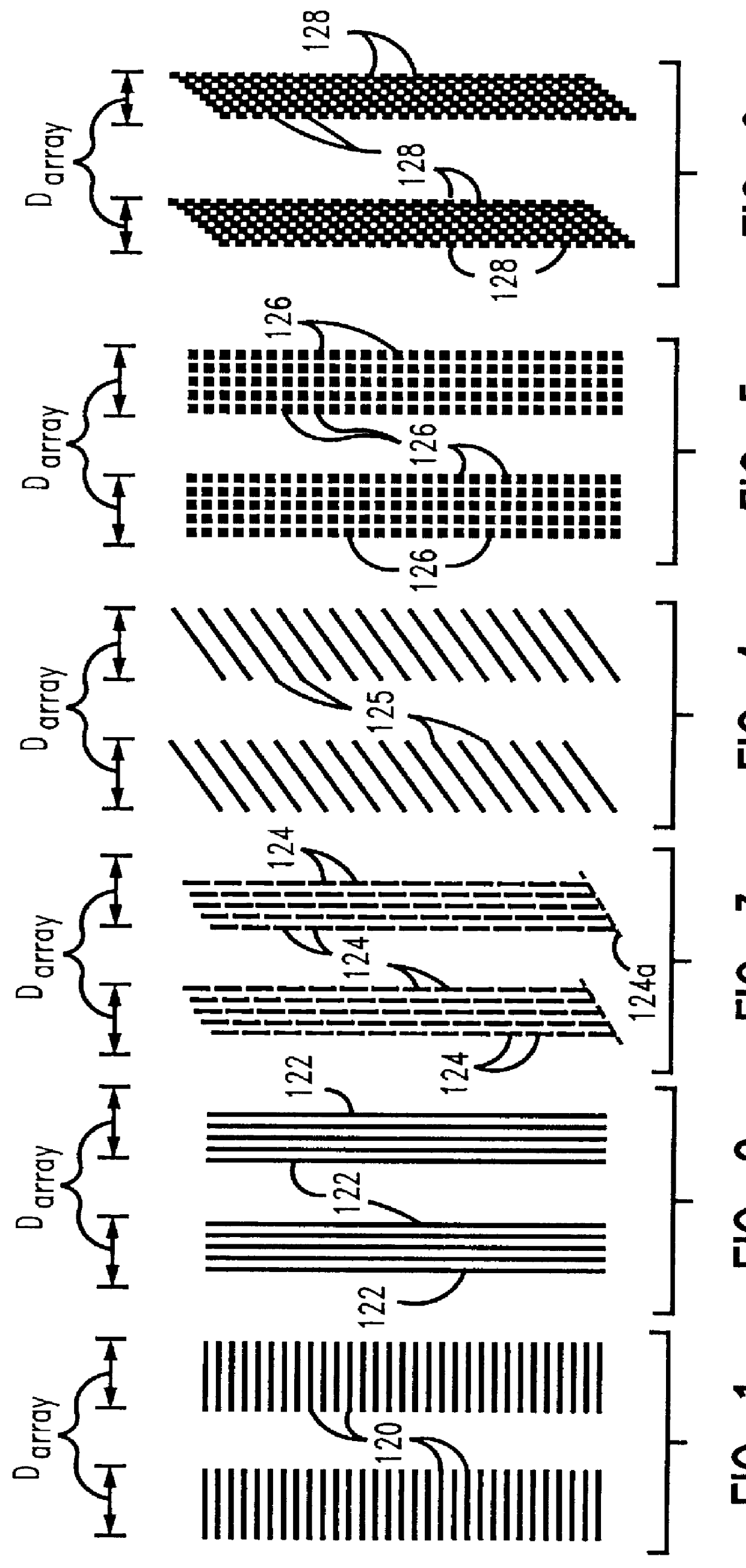
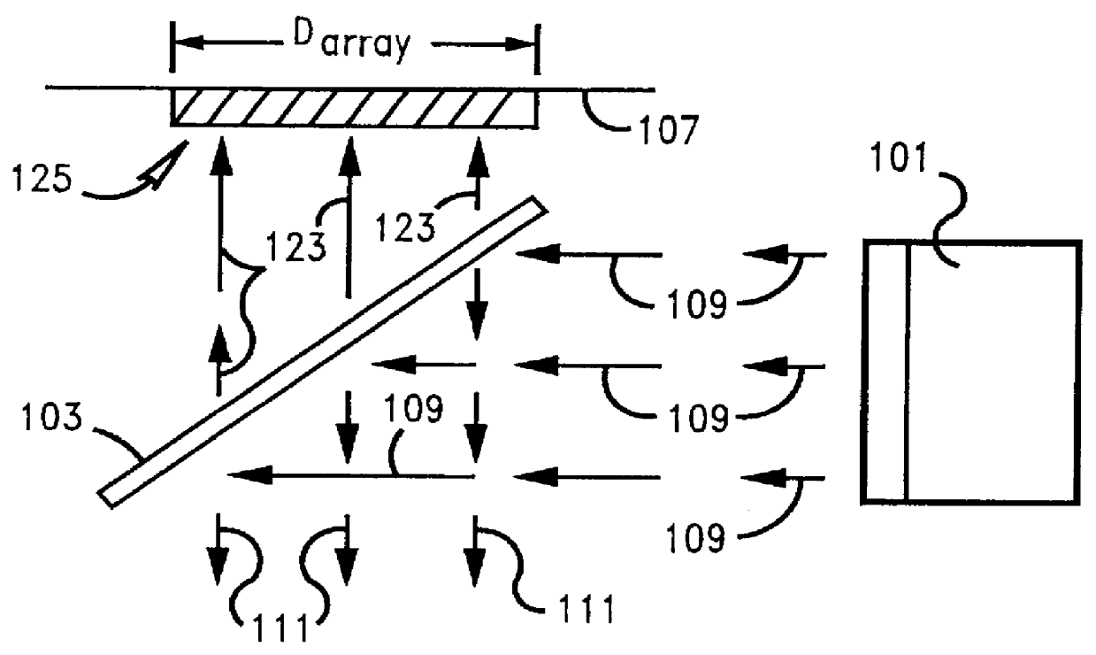
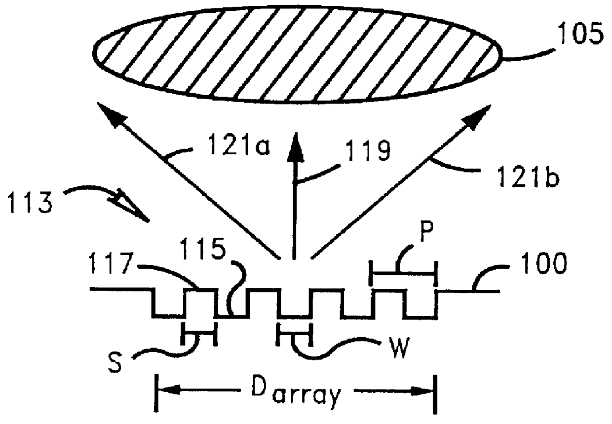
The present invention utilizes a pattern control system based on the measurement of complementary tone patterns, i.e., patterns in which the tone is reversed. The "tone" of a lithographic pattern is determined by the presence or absence of resist material which is normally deposited in a layer or film on the surface of the substrate to be etched. Patterns are either resist shapes on a clear background or the absence of resist shapes (i.e., spaces) in a background of resist material. Complementary tone patterns can be formed by interchanging the areas that are exposed during the lithographic process.

These tone patterns may be created in resist material by preparing masks with opaque and transparent areas corresponding to ...


PUM


Abstract

A target for measurement of critical dimension bias on a substrate formed by a lithographic process comprises three sets of contrasting arrays of elements on the substrate. Each of the arrays has a plurality of spaced parallel elements contrasting with the substrate. Ends of the contrasting elements are aligned along parallel lines forming opposite array edges, with the length of the contrasting elements comprising the array width. The array edges are measurable by microscopy without resolution of individual elements of the array. The three arrays are spaced apart in the X- or Y-direction such that critical dimension bias may be measured by comparing the centerline of a first distance measured from one edge of the first array to one edge of the third array to the centerline of a second distance measured from one edge of the second array to one edge of the third array, with the centerlines being measured without resolution of the individual array elements.

Description

1. Field of the InventionThe present invention relates generally to manufacturing processes requiring lithography and, more particularly, to targets used to monitor lithographic and etch process conditions used in microelectronics manufacturing which is particularly useful for monitoring pattern features with dimensions on the order of less than 0.5 micron.2. Description of Related ArtControl of a lithographic imaging process requires the optimization of exposure and focus conditions in lithographic processing of product wafers. Likewise, it is also important to optimize etching and other parameters on product wafers. The current solution to the above problems entails the collection and analysis of critical dimension measurements using SEM metrology on multiple pattern types at multiple locations within the chip, and from chip-to-chip. This method is slow, expensive and error-prone. It usually requires the exposure of multiple focus-exposure and etching matrices on product wafers.Ge...

Claims


Application Information

Patent Timeline
IPC IPC(8): G03F7/20
CPCG03F7/70625
Inventor AUSSCHNITT, CHRISTOPHER P.
Owner IBM CORP
Why Eureka
Try Eureka