Methods and apparatus for imaging with multimode optical fibers

a multi-mode optical fiber and imaging method technology, applied in the direction of optical radiation measurement, instruments, spectrometry/spectrophotometry/monochromators, etc., can solve the problems of limited system, limited light transmission, and achieved at the expense of resolution

Active Publication Date: 2015-01-15
ECOLE POLYTECHNIQUE FEDERALE DE LAUSANNE (EPFL)
View PDF13 Cites 131 Cited by
  • Summary
  • Abstract
  • Description
  • Claims
  • Application Information

AI Technical Summary

Problems solved by technology

In both cases, these systems are limited either by their size, flexibility, imaging resolution or their weak light collection.
However, this is achieved at the expense of resolution.
However, light propagation through a multimode fiber produces a speckle pattern and thus a specific spatial excitation / illumination through a MM fiber is a challenge.
These two aspects have always limited their use for light transmission, and particularly for fiber-based imaging.
However such a technique has not been shown to work with very high number of modes.

Method used


Image

  • Methods and apparatus for imaging with multimode optical fibers
  • Methods and apparatus for imaging with multimode optical fibers
  • Methods and apparatus for imaging with multimode optical fibers

Examples


Embodiment Construction

[0128]In the following description, reference is made to the accompanying drawings, which form a part hereof, and in which are shown, by way of illustration, several embodiments of the present invention. It is understood that other embodiments may be utilized and structural changes may be made without departing from the scope of the present invention. In the text, the use of the term multimode fibers comprises any multimode waveguide element.

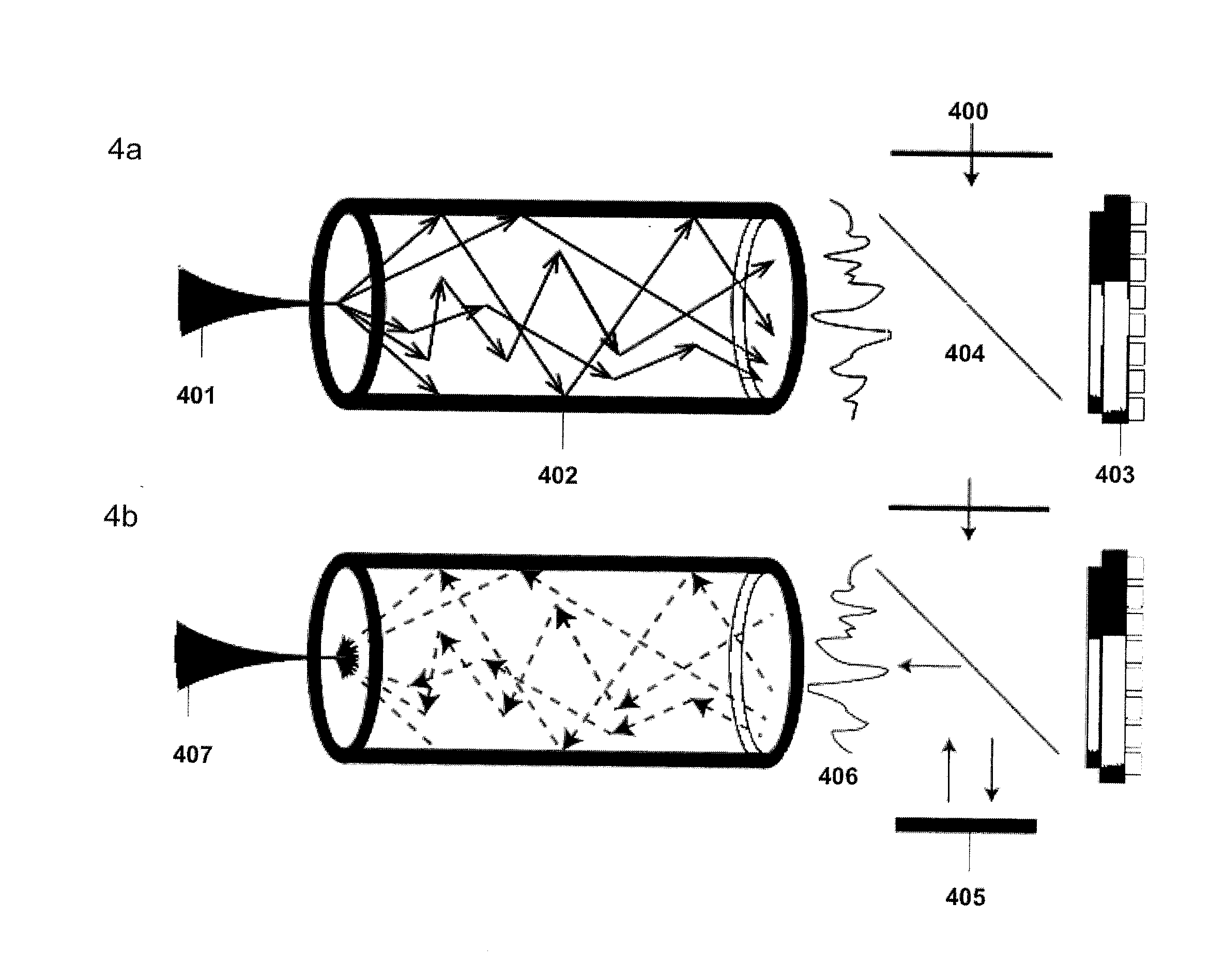
[0129]The lensless multimode fiber based imaging system and apparatus allows for several embodiments including 1) a system for delivering a sequence of complex illumination patterns such as, but not limited to a diffraction limited spot at the distal end of a MM fiber and / or 2) a system for collecting scattered light and constructing an image through a multimode fiber and / or 3) a system for performing non-linear imaging through a multimode fiber such as but not limited to, Raman and two photon and / or 4) a system to achieve super-resolution imagi...


PUM

PropertyMeasurementUnit
diameteraaaaaaaaaa
core diameteraaaaaaaaaa
diameteraaaaaaaaaa

Abstract

A multimode waveguide illuminator and imager relies on a wave front shaping system that acts to compensate for modal scrambling and light dispersion by the multimode waveguide. A first step consists of calibrating the multimode waveguide and a second step consists in projecting a specific pattern on the waveguide proximal end in order to produce the desire light pattern at its distal end. The illumination pattern can be scanned or changed dynamically only by changing the phase pattern projected at the proximal end of the waveguide. The third and last step consists in collecting the optical information, generated by the sample, through the same waveguide in order to form an image. Known free space microscopy technique can be adapted to endoscopy with multimode waveguide, such as, but not limited to, fluorescence imaging or Raman spectroscopy or imaging, 3D linear scattering imaging or two-photon imaging. Super-resolution, i.e., resolution below the diffraction limit, is achieved for example but not limited to, using the STimulated Emission Depletion microscopy (STED) technique or the Structured Illumination Microscopy (SIM) technique or a stochastic illumination based method (PALM, STORM) in combination with the multimode waveguide imaging method.

Description

FIELD OF THE INVENTION[0001]The present invention relates to producing high-resolution images through a multimode fiber such as but not limited to endoscopic imaging. Embodiments of the present invention relate generally to imaging through multimode fibers, and in particular, to methods and apparatus for imaging through a multimode fiber. The illumination is delivered via a multimode fiber core and the optical information backscattered by a sample is collected and carried optically through the same said multimode fiber core prior to conversion to a digital image. After transmission of the scattered light through the multimode fiber, the digital image is formed by first converting the optical signal to an electronic signal by a single or multi-element photodetector and then by processing the said electronic signal. The multimode fiber imaging system may be passive, i.e., contain no active elements at the distal end of the multimode fiber or alternatively it may contain actuators / sens...

Claims


Application Information

Patent Timeline
Patent Type & Authority Applications(United States)
IPC IPC(8): H04N1/40G02B6/028G02F1/313G02F1/01G01J3/44G01J3/02
CPCG02F1/313H04N1/40G02B6/0288G01J3/0218G02F1/0136G02F1/011G01J3/44G02B23/26G02B26/06G03H1/0005G02B27/58H04B10/2581G03H2001/0434G03H1/2286G03H1/2294G03H2001/0447A61B1/07
Inventor PAPADOPOULOS, IOANNISFARAHI, SALMAMOSER, CHRISTOPHEPSALTIS, DEMETRI
Owner ECOLE POLYTECHNIQUE FEDERALE DE LAUSANNE (EPFL)
Why Eureka
Try Eureka