Portable shelters, related shelter systems, and methods of their deployment

a technology of portable shelters and related shelter systems, applied in the field of portable shelters, shelter systems, and methods of portable shelter deployment, can solve the problems of increasing victims' misery, housing gaps that exacerbate recovery efforts, and many houses were destroyed

Inactive Publication Date: 2011-10-25
NEWCO SHELTER CORP +1
View PDF49 Cites 28 Cited by
  • Summary
  • Abstract
  • Description
  • Claims
  • Application Information

AI Technical Summary

Benefits of technology

[0011]The present invention provides a better solution to the housing gap—comprehensive, rapid-deploy shelters and shelter systems with a variety of customizable configurations to meet any challenge related to the actual disaster or deployment site. The systems of the present invention comprise shelter units, accessories, and supporting infrastructure that can be easily transported on a rapid timeframe. The systems' deployment sites can keep displaced populations as close to their homes as safely possible. The individual shelter units of the systems of the present invention provide safe, private sleeping arrangements for individuals and families. Each unit could offer power and climate control and would offer security, durability, and expandability for longer-term deployments. System components can endure long-term storage in warehouse-type environments, be rapidly transported through conventional means, and be fully deployable in large numbers in less than 24 hours. Also, the financial impact of a large-scale disaster can be somewhat tapered by creating a complete system for the very purpose of emergency housing that is easily transportable, reusable, and maintainable.
[0016]When not in use, both of the shelter concepts are able to nest with similar shelters and flat pack for storage and transport. They can be stored efficiently until they are needed due to their rugged, all weather design which allows them to endure very long term storage spans without decay or wear. All system components can be stored in centralized warehouse type facilities that could serve as distribution centers. These facilities would be located near major thoroughfares, rail lines, airports, or ports. These distribution centers may be stocked with certain system components to allow for a more appropriate response to the typical types of disasters in a particular region. System components can then be rapidly loaded and transported from these storage facilities to the predetermined deployment sites using various modes of transit that may be available at a given moment or location.
[0022]Yet another embodiment of the present invention is a method for rapid deployment of temporary housing comprising providing a shelter system which comprises a plurality of collapsible shelter structures wherein each shelter structure is comprised of a substantially uniform rigid top frame structure and a substantially uniform rigid bottom frame structure, collapsing the shelter structures by urging each top frame structure and its respective bottom frame structure closer together, loading a plurality of the shelter structures on one or more transportation units, and unloading and expanding the collapsed shelter structures.
[0023]Still another embodiment of the present invention is a method for rapid deployment of temporary housing comprising providing a shelter system which comprises a plurality of stackable shelter units wherein each shelter unit is comprised of a substantially uniform rigid top and a removable rigid bottom, separating each rigid top from its respective rigid bottom, stacking the rigid tops and / or the rigid bottoms, loading the stacked rigid tops and stacked rigid bottoms on one or more transportation units, and unloading and assembling the rigid tops and rigid bottoms to form the shelter units.

Problems solved by technology

Until now, humanitarian aid organizations, disaster relief agencies, and most governments were missing a critical tool for emergency recover efforts—readily deployable housing for displaced individuals and families.
Currently, there are no emergency housing systems that can address all four periods and yet be flexible enough to transition from one housing period to the next as needs change, creating a housing gap that exacerbates recovery efforts and increases victims' misery.
In Louisiana, many houses also were destroyed in the southeastern parishes, and many New Orleans residents, who were unable to evacuate before the storm, were stranded at the Louisiana Superdome or New Orleans Convention Center in detestable conditions.
However, each of these systems has major drawbacks.
Specifically, regarding the housing vouchers, they proved to be inadequate at sheltering large populations for several obvious reasons.
By redistributing a large number of people in such an abrupt and rapid manner, regional infrastructure is overwhelmed and cannot maintain day-to-day operations.
Housing vouchers present numerous problems with fraud, abuse, and the cost of living in the varying locations to which families are displaced.
While these ships do allow a number of people to stay in a compact, self-sufficient area for an extended time period, the cruise ships are limited to deep-water ports for deployment, can only handle a small amount of the population from a major disaster, and must be leased or rented from private or foreign fleets.
One governmental agency was widely criticized for the slow and inadequate response in providing temporary housing to residents in need in Mississippi and Louisiana and for the high cost of the travel-type trailers provided to residents.
Also, the trailers are not designed for long-term storage and are too bulky to efficiently store in large numbers.
Moreover, the trailers were of the type that one truck could only pull one trailer, which resulted in the trailers being individually delivered to individuals and families in Mississippi and Louisiana using individual pickup trucks, which resulted in slow deployment of these trailers to those residents in need of temporary housing.
Therefore, it is clear that past solutions have many flaws without even taking into consideration the sheer costs associated with each.

Method used


Image

  • Portable shelters, related shelter systems, and methods of their deployment
  • Portable shelters, related shelter systems, and methods of their deployment
  • Portable shelters, related shelter systems, and methods of their deployment

Examples


Embodiment Construction

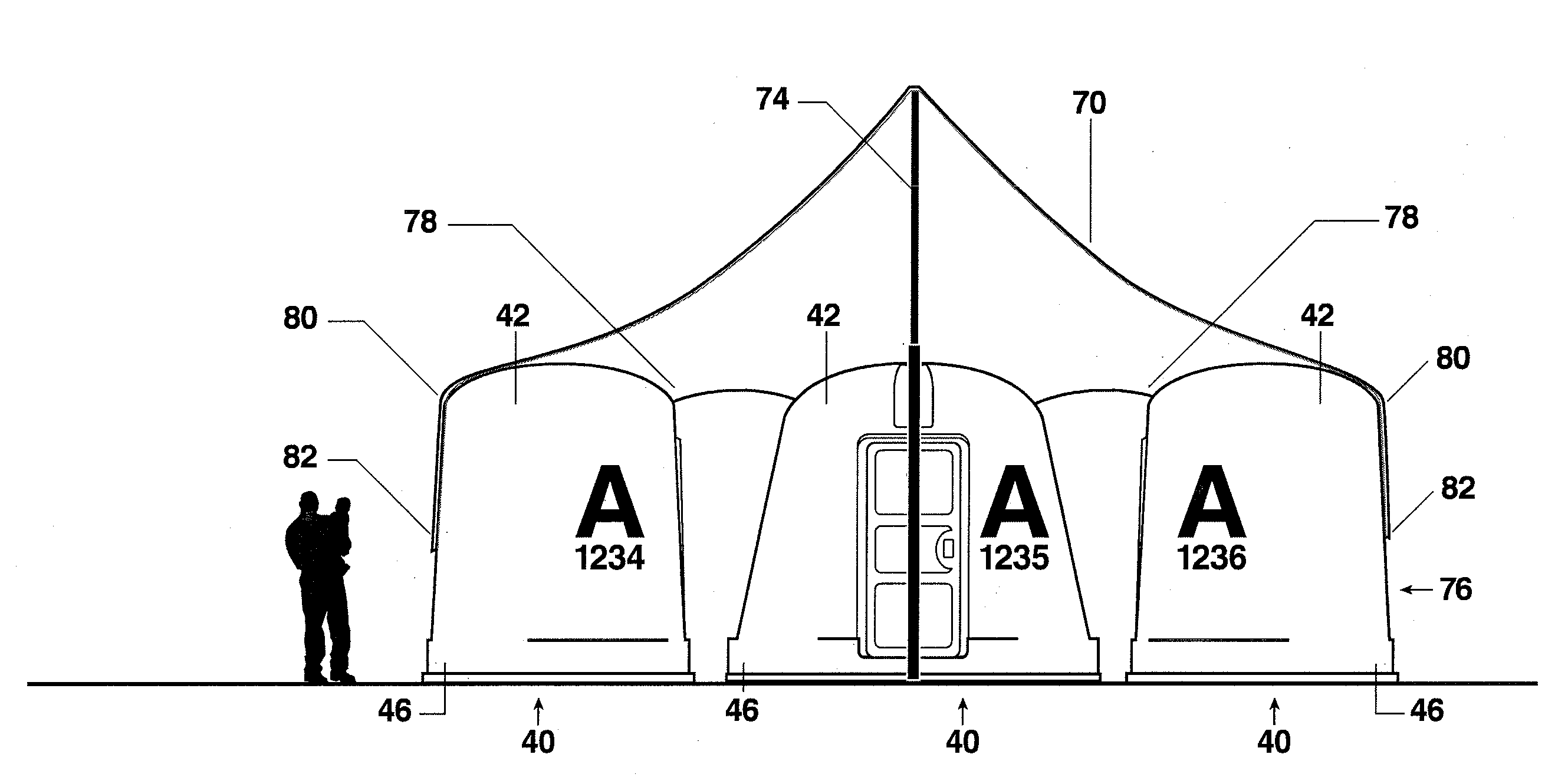
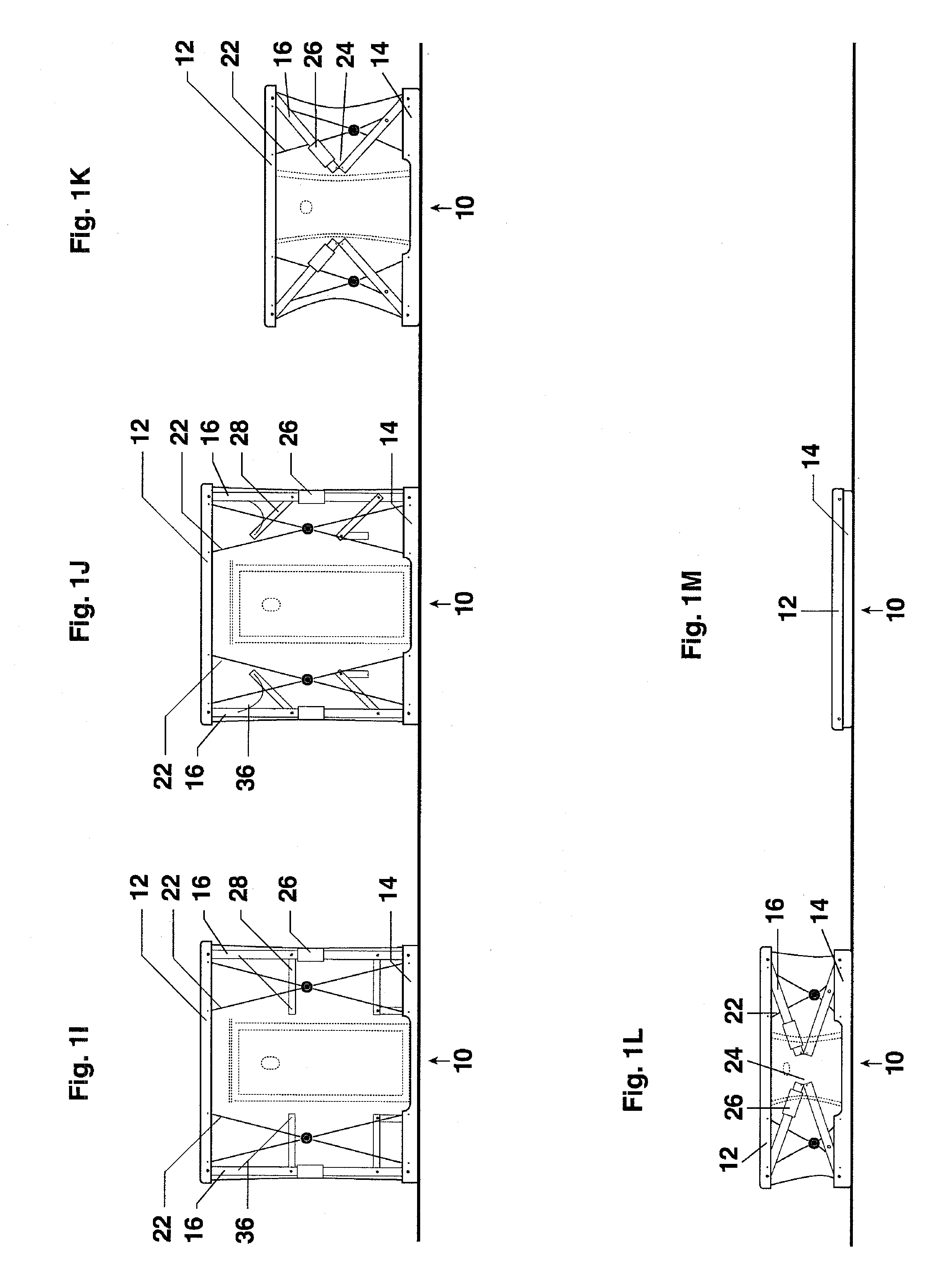
[0033]Referring now to FIGS. 1A-1R, these figures depict one particular embodiment of the present invention, specifically a soft-wall shelter of this invention. In the absence of any covering, FIG. 1A represents the plan view of shelter, FIG. 1B a front section of the shelter, FIG. 1C a side section of the shelter, and 1D a rear section of the shelter. FIG. 1E depicts a plan view of the shelter, FIG. 1F a front elevation view of the shelter, FIG. 1G a side elevation view of the shelter, and FIG. 1H a rear elevation view of the shelter. FIGS. 1I-1M represent the steps of collapsing a shelter from being erect to being completely collapsed and ready for transport or storage. Finally, FIG. 1N is a cut-away view of a particular embodiment of a soft-wall shelter. In this particular embodiment of the present invention a shelter 10 comprises a rigid top frame structure 12 which is generally rectangular in shape, a rigid bottom frame structure 14 which is generally the same size and shape of...


PUM

PropertyMeasurementUnit
shapeaaaaaaaaaa
sizeaaaaaaaaaa
heightaaaaaaaaaa

Abstract

Portable shelters, shelter systems, and methods of deployment of such shelters are described. The shelters or housing units may be deployed in emergency housing situations and may be grouped into systems of shelters. One particular embodiment comprises a rigid top frame structure, a rigid bottom frame structure, and one or more collapsible support arms connecting the top frame structure to the bottom frame structure. The frame structures and the collapsible support arm(s) are sized and configured to form a shelter frame when the collapsible support arm(s) are in a fully extended position, and the top frame structure is brought into proximity with the bottom frame structure when the collapsible support arm(s) are in a collapsed position. Methods of rapid deployment of the shelters and systems of shelters are also described.

Description

REFERENCE TO RELATED APPLICATION[0001]This application claims the benefit and priority of U.S. Provisional Application No. 60 / 912,079, filed Apr. 16, 2007, the disclosure of which is incorporated herein by reference.TECHNICAL FIELD[0002]This invention relates to the field of portable shelters, shelter systems, and methods of portable shelter deployment. Specifically, this invention relates to temporary housing shelters which may be deployed in emergency housing situations.BACKGROUND[0003]Until now, humanitarian aid organizations, disaster relief agencies, and most governments were missing a critical tool for emergency recover efforts—readily deployable housing for displaced individuals and families. After most natural and man-made disasters, housing needs can be broken into three main periods: short-term housing, medium-term housing, and long-term housing. A few types of specific disasters can be forecast, such as hurricanes, which create a different housing need and a fourth period...

Claims


Application Information

Patent Timeline
Patent Type & Authority Patents(United States)
IPC IPC(8): E04H15/18
CPCE04H1/1205E04H9/14E04H15/02E04H15/18E04H15/48E04B1/34331E04B1/34336E04B1/34352E04B1/34384E04H15/008Y10T29/49826Y10T29/49819Y02A50/00
Inventor MCDANIEL, JR., MICHAEL D.
Owner NEWCO SHELTER CORP
Why Eureka
Try Eureka