Supercharge Your Innovation With Domain-Expert AI Agents!

Ferrite material and method for producing ferrite material

a technology of ferrite material and ferrite core, which is applied in the direction of magnetic materials, loop antennas with ferromagnetic cores, magnetic bodies, etc., can solve the problems of difficult to directly wind a coil on the core, difficult to remove noise from materials, and low impedance, so as to achieve high specific resistance, high impedance, and efficient inhibit the transmission of noise

Active Publication Date: 2011-10-25
HITACHI METALS LTD
View PDF2 Cites 0 Cited by
  • Summary
  • Abstract
  • Description
  • Claims
  • Application Information

AI Technical Summary

Benefits of technology

[0013]An object of the present invention is to provide a ferrite material having high impedance in a high-frequency band, so high specific resistance to enable to be directly wound on a core, and small change of magnetic characteristics by external stress, producible at a low cost, and usable for core materials of coil parts such as noise filters, choke coil, or electric wave absorbers.
[0032]It is also made possible to provide an electric wave absorber having excellent electric wave absorption capability in a high-frequency band at a low cost by dispersing the ferrite powders of the present invention in a resin and molding the resulting mixture.

Problems solved by technology

Accordingly, the impedance is lowered at frequency of 10 MHz or more and the materials are difficult to be used for removing noise in a high-frequency band of 30 MHz or more.
Furthermore, since the specific resistance is low, it is also difficult to directly wind a coil on a core and production steps such as a step of inserting an insulating material between the core and the coil are increased and the miniaturization is thus difficult.
However, since the Ni—Zn-based ferrites have high magnetostriction and show large change of magnetic characteristics by external stress, if a coiling is firmed on a ferrite core and thereafter molding with a resin is carried out in order to improve the reliability, there is a problem of changing magnetic permeability by the stress.
Further, since costly Ni is contained as a main component, there is another problem that production cost is high.

Method used


Image

  • Ferrite material and method for producing ferrite material
  • Ferrite material and method for producing ferrite material
  • Ferrite material and method for producing ferrite material

Examples


example 1

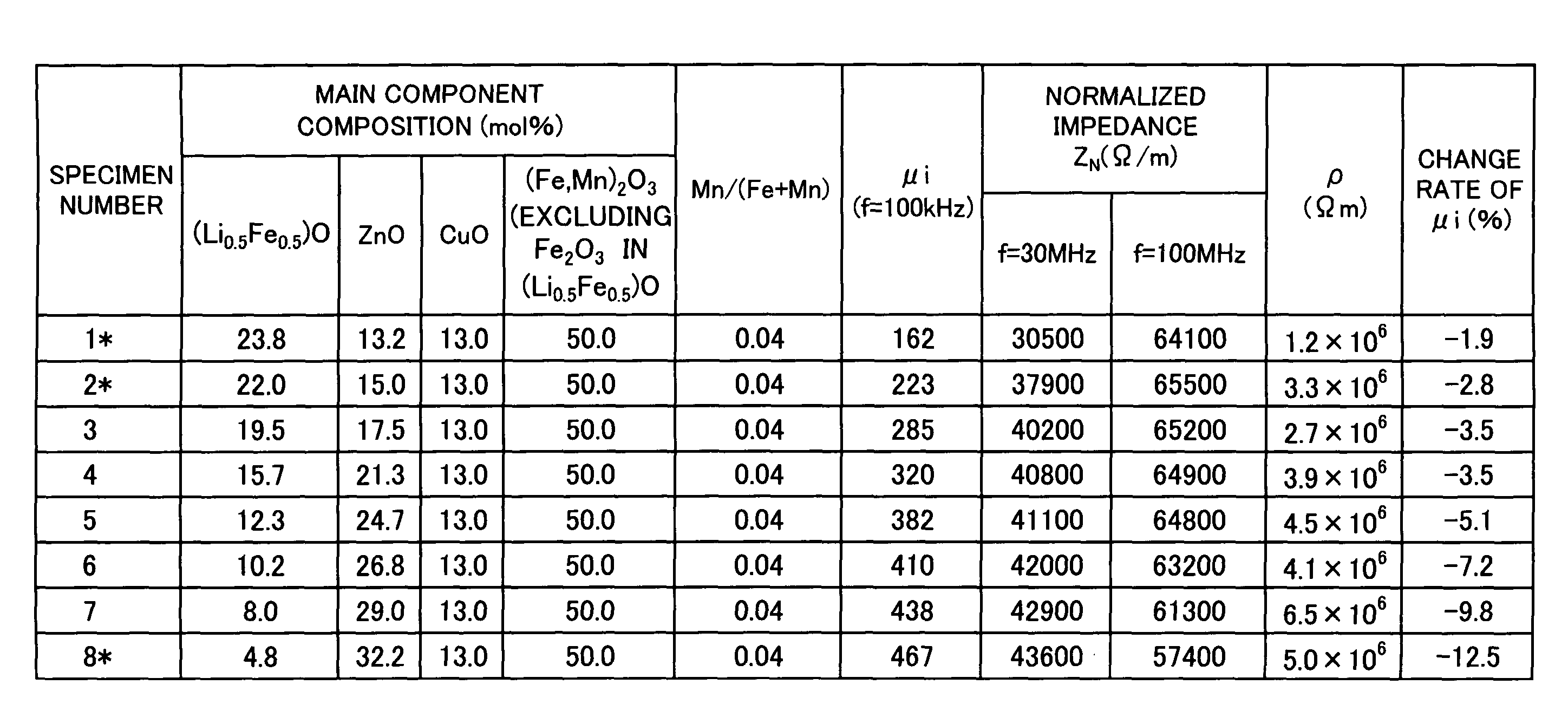
[0060]Example 1 is for proving the reason of limitation of composition of x denoting the content ratio of ZnO in a ferrite material of the present invention.

[0061]Carbonate powders and oxide powders being starting raw materials were weighed and mixed to give final compositions of the respective compositions as shown in FIG. 1 ((Li0.5Fe0.5)O, ZnO, (Mn, Fe)2O3, and CuO shown by mol %, in the composition formula, 0.01 for x, y, and z corresponds to 1 mol %) and fired at 900° C. for 3 hours in an atmospheric air. The obtained calcinated powders were wet-grinded to give a size from 0.5 μm to 1.5 μm, and thereafter dried.

[0062]The obtained powders were mixed with 1 wt. % of polyvinyl alcohol and granulated to obtain granulated powders, and then the granulated powders were molded respectively into a ring shape of external diameter of 9 mm×inner diameter of 4 mm×thickness of 3 mm; a plate shape of long side of 20 mm×short side of 10 mm×thickness of 5 mm; and a frame shape of external frame ...

example 2

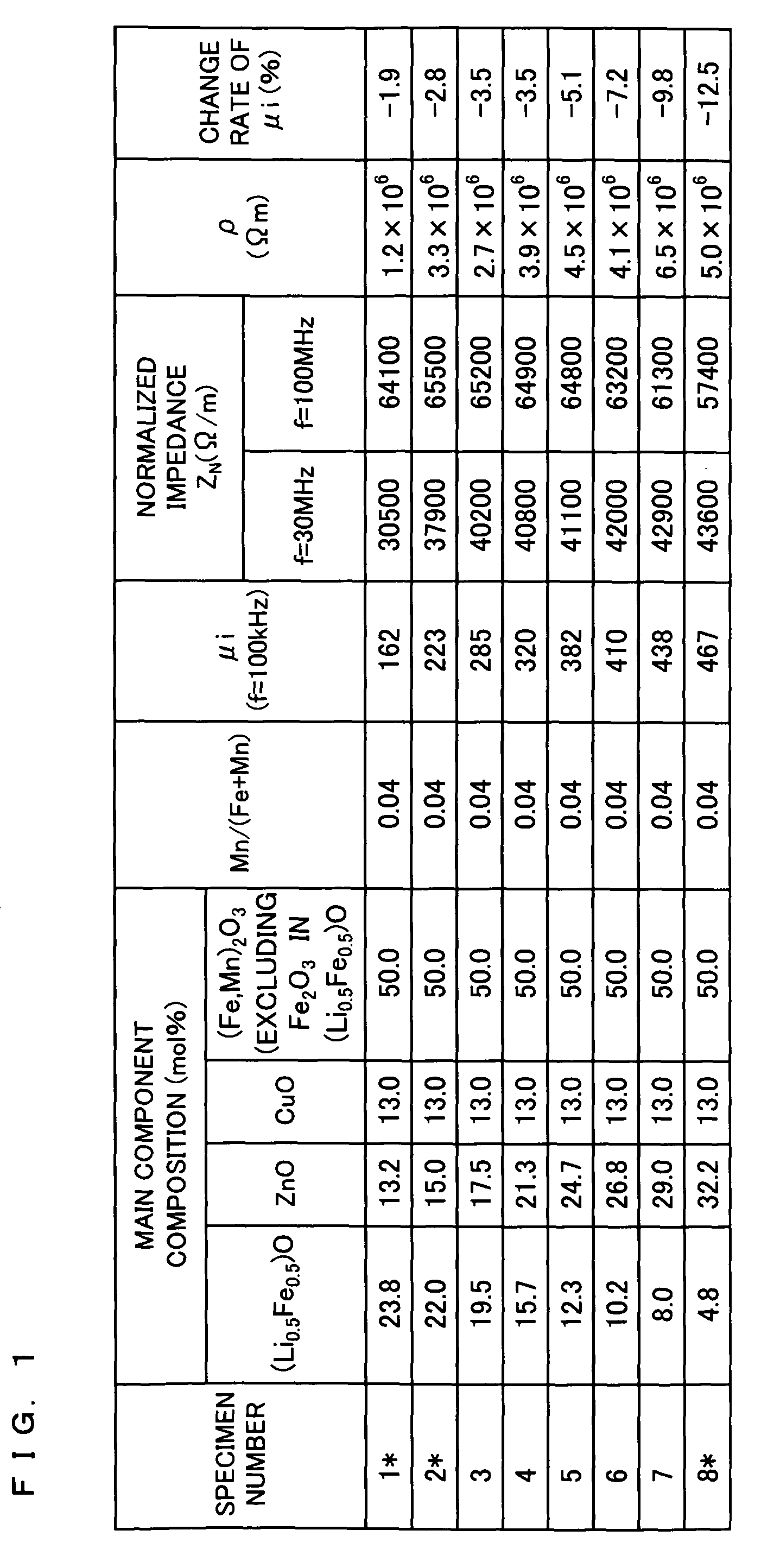
[0068]Example 2 is for proving the reason of limitation of composition of y denoting the content ratio of (Mn, Fe)2O3 in a ferrite material of the present invention.

[0069]Experiments were carried out in the same manner as Example 1, except that various compositions as final compositions shown in FIG. 2 were used. The results are shown in FIG. 2.

[0070]As being seen from FIG. 2, with respect to the ferrite materials having the composition formula of (1-x-y-z)(Li0.5Fe0.5)O.xZnO.y(Mn, Fe)2O3.zCuO, a=Mn / (Mn+Fe), it can be understood that ferrite materials having both 40000 Ω / m or more as the normalized impedance ZN at 30 MHz and 60000 Ω / m or more as the normalized impedance ZN at 100 MHz as well as satisfying specific resistance of 106 Ωm or more have been obtained while a range of the content ratio of (Mn, Fe)2O3 being from 0.475 to 0.51. Further, as being seen from the change rate of μi, it can be understood that ferrite materials with small change rate of the initial magnetic permeabi...

example 3

[0071]Example 3 is for proving the reason of limitation of composition of z denoting the content ratio of CuO, being one of characteristics of a ferrite material of the present invention.

[0072]Experiments were carried / out in the same manner as Example 1, except that various compositions as final compositions shown in FIG. 3 were used. The results are shown in FIG. 3.

[0073]As being seen from FIG. 3, with respect to the ferrite materials having the composition formula of (1-x-y-z)(Li0.5Fe0.5)O.xZnO.y(Mn, Fe)2O3.zCuO, a=Mn / (Mn+Fe), it can be understood that ferrite materials having both 40000 Ω / m or more as the normalized impedance ZN at 30 MHz and 60000 Ω / m or more as the normalized impedance ZN at 100 MHz as well as satisfying specific resistance of 106 Ωm or more have been obtained while a range of the content ratio of CuO being from 0.07 to 0.22. Further, as being seen from the change rate of μi, it can be understood that ferrite materials with small change rates of the initial mag...


PUM

PropertyMeasurementUnit
pressureaaaaaaaaaa
temperatureaaaaaaaaaa
frequencyaaaaaaaaaa

Abstract

The invention provides a ferrite material (ferrite sintered body, ferrite powders) having a composition formula of (1-x-y-z)(Li0.5Fe0.5)O.xZnO.y(Mn, Fe)2O3.zCuO, wherein x, y, z, and a satisfy 0.175≦x≦0.29; 0.475≦y≦0.51; 0.07≦z≦0.22; and 0.02≦a≦0.055 in a case of a=Mn / (Mn+Fe). At least one of Co oxide, Co hydroxide, and Co carbonate in an amount of 1 wt. % or less on the basis of CoO may be contained in 100 wt % of the ferrite material. The ferrite material has a normalized impedance ZN of 40000 Ω / m or more at 30 MHz and a normalized impedance ZN of 60000 Ω / m or more at 100 MHz as well as a specific resistance of 106 Ωm or more.

Description

CROSS-REFERENCE TO RELATED APPLICATIONS[0001]This Nonprovisional application claims priority under 35 U.S.C. §119(a) on Patent Application No. 2007-225688 filed in Japan on Aug. 31, 2007 and No. 2008-208663 filed in Japan on Aug. 13, 2008, the entire contents of which are hereby incorporated by reference.BACKGROUND OF THE INVENTION[0002]1. Field of the Invention[0003]The present invention relates to a ferrite material having high impedance in a high-frequency band, and a method for producing the same.[0004]2. Description of Related Art[0005]Various types of noise filters for inhibiting transmission of noise of electronic appliances have been proposed and employed, and as filters for inhibiting transmission of signal components in a high-frequency band, for example, noise filters obtained by winding coils on ferrite cores have been known.[0006]For these noise filters, magnetic impedance of ferrite materials has be utilized, and along with the miniaturization of various types of elect...

Claims


Application Information

Patent Timeline
Patent Type & Authority Patents(United States)
IPC IPC(8): H01F1/34C04B35/26
CPCC04B35/2616C04B35/265H01F1/344H01F41/0246H01Q7/06H01Q7/08C04B2235/3203C04B2235/3262C04B2235/3275C04B2235/3281C04B2235/3284C04B2235/528C04B2235/5436C04B2235/6585C04B2235/95H01F1/37
Inventor TADA, TOMOYUKIMIYOSHI, YASUHARUYANAGIHARA, TAKESHI
Owner HITACHI METALS LTD
Features
  • R&D
  • Intellectual Property
  • Life Sciences
  • Materials
  • Tech Scout
  • Unparalleled Data Quality
  • Higher Quality Content
  • 60% Fewer Hallucinations
Learn More