Apparatus and method for intermediate image-formation of information propagating as wave motion passing through open hole and for image pick-up

a wave motion and image-forming technology, applied in the field of apparatus and method for intermediate image-forming of information propagating as wave motion passing through open hole and for image pickup, can solve the problems of blurred formed image and distortion, and achieve the effects of shortening the wavelength, reducing the blurring by diffraction, and reducing the distance between the opening and the formed

Inactive Publication Date: 2011-10-25
JAPAN SCI & TECH CORP
View PDF9 Cites 0 Cited by
  • Summary
  • Abstract
  • Description
  • Claims
  • Application Information

AI Technical Summary

Benefits of technology

[0003]In the present image-forming systems using an opening and having an interrupter that intercepts a wave motion, the opening being made in the interrupter, an image is formed geometrically due to rectilinear propagation of a wave front. However, the formed image is blurred due to diffraction nature of the waves. The shorter the wavelength is, the smaller the blurring by the diffraction becomes. In the case of electromagnetic waves, blurring caused by diffraction becomes smaller as the wavelength becomes shorter from visible light to extreme ultraviolet light, soft X-rays, hard X-rays, and gamma rays. In the case of quantum waves, which are also a wave motion due to dual wave-particle nature of particles having mass, this blurring is much smaller than that of electromagnetic waves in general. These image-formation systems, using an opening, have the characteristic that the longer the distance between the opening and the formed image is, the higher and the larger the optimum spatial resolution and the optimum diameter of the opening become. In general, waves with particular wave length which we aim to detect can be different from the waves that an appropriate and feasible two-dimensional image pick-up device can detect. Therefore, an intermediate wave-converting surface is provided between an opening and a two-dimensional image pick-up device to form an undistorted image on the wave-converting surface. The image is converted into waves with a certain wavelength, normally light, which is an electromagnetic wave with a wavelength that, for example, an inexpensive optical CCD camera can detect. The image is then picked up by the CCD camera. In this step, since the CCD camera forms an image using, for example, optical lenses, distortion can occur. The distortion in this case is characterized by the lenses of the CCD camera. These characteristics are described in advance by a one-to-one function between a coordinate system on the intermediate wave-converting surface and a coordinate on the two-dimensional image pick-up element. The distortion of the image formed by the two-dimensional image pick-up element is corrected using this function in real time or later with a computer. In this way, a numeric-value image having no distortion can be stored on a recording medium. In addition, this intermediate surface can act as a means to pick-up the image itself with properly distributed detectors on the intermediate surface. The surface also can act as a means to make the field of view of the object from the opening wide or narrow by making the distance between the opening and the surface short or long. The waves include electromagnetic waves, quantum waves, and waves corresponding to the actual mass or media motion, such as sound waves, and all other kinds of waves. Therefore, the intermediate wave-converting surface acts as a means not only to convert a wave length but also to convert the entity and nature of a wave.
[0010][5] A method for picking up an image by using a combination of an opening and a two-dimensional image pick-up device according to [1] or [2]. By using the waves from the opening, the diameter of the opening is reduced, and the distance between the opening and the image-forming surface of the intermediate wave converter is reduced.

Problems solved by technology

However, the formed image is blurred due to diffraction nature of the waves.
In this step, since the CCD camera forms an image using, for example, optical lenses, distortion can occur.

Method used


Image

  • Apparatus and method for intermediate image-formation of information propagating as wave motion passing through open hole and for image pick-up
  • Apparatus and method for intermediate image-formation of information propagating as wave motion passing through open hole and for image pick-up
  • Apparatus and method for intermediate image-formation of information propagating as wave motion passing through open hole and for image pick-up

Examples


first embodiment

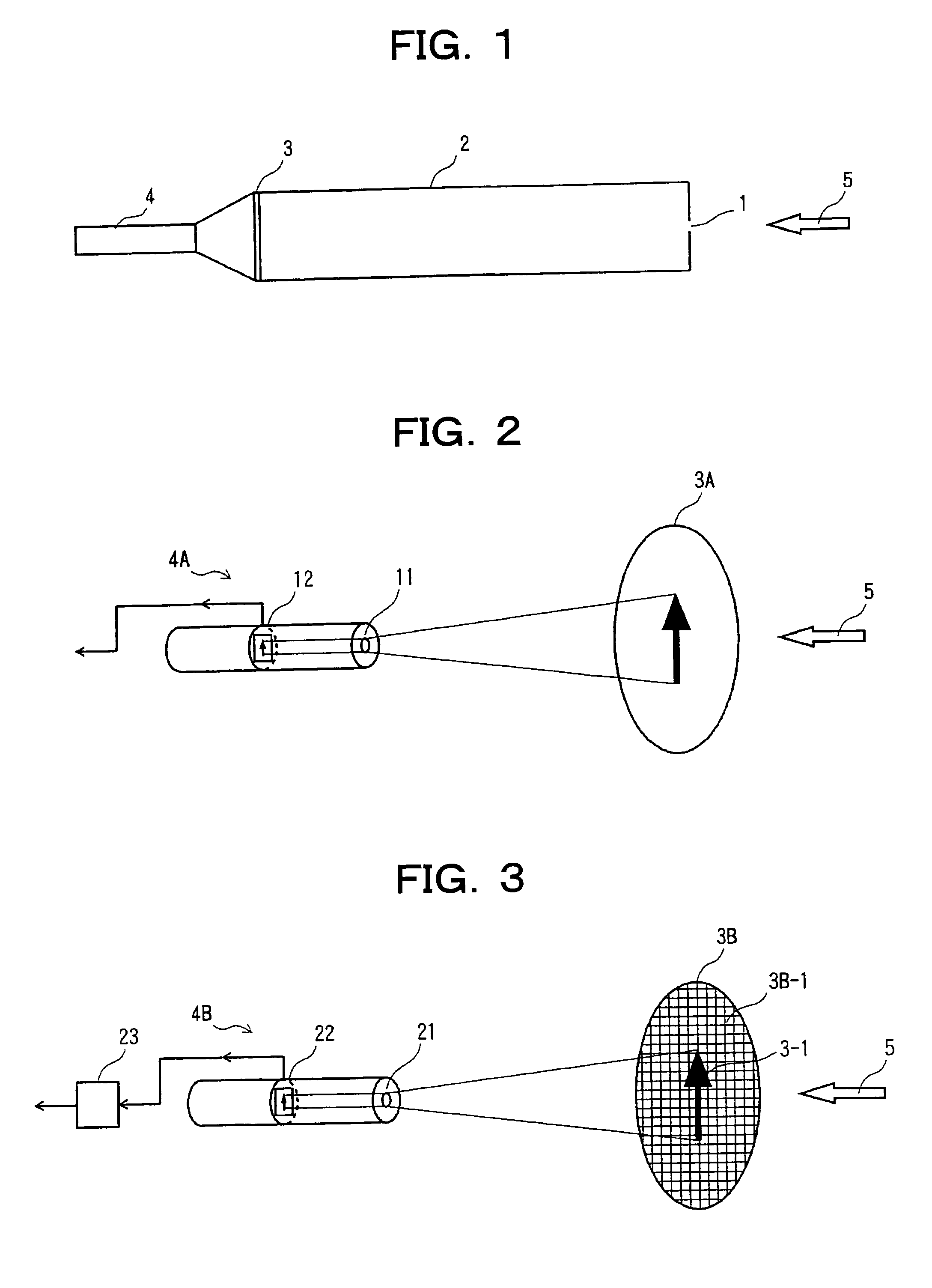
[0029]FIG. 2 is a schematic view of an image pick-up optical apparatus combining an opening and a CCD according to the present invention.

[0030]In this figure, an incident electromagnetic wave 5 is converted into visible light by the wave-converting surface 3A (that has, for example, dot-like elements that emit light detectable wave length when irradiated with the electromagnetic wave 5). The converted visible light passes through a lens image-forming system 11, is picked up by the CCD image-forming surface 12, and is output as an image.

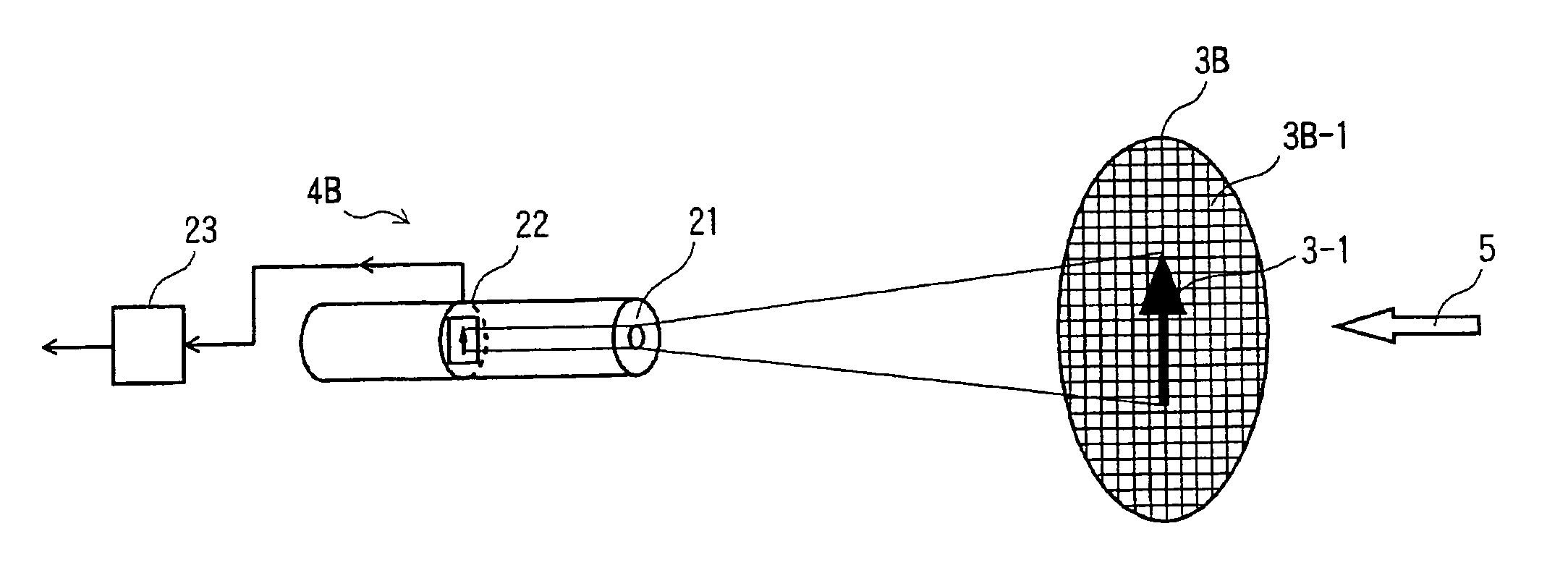
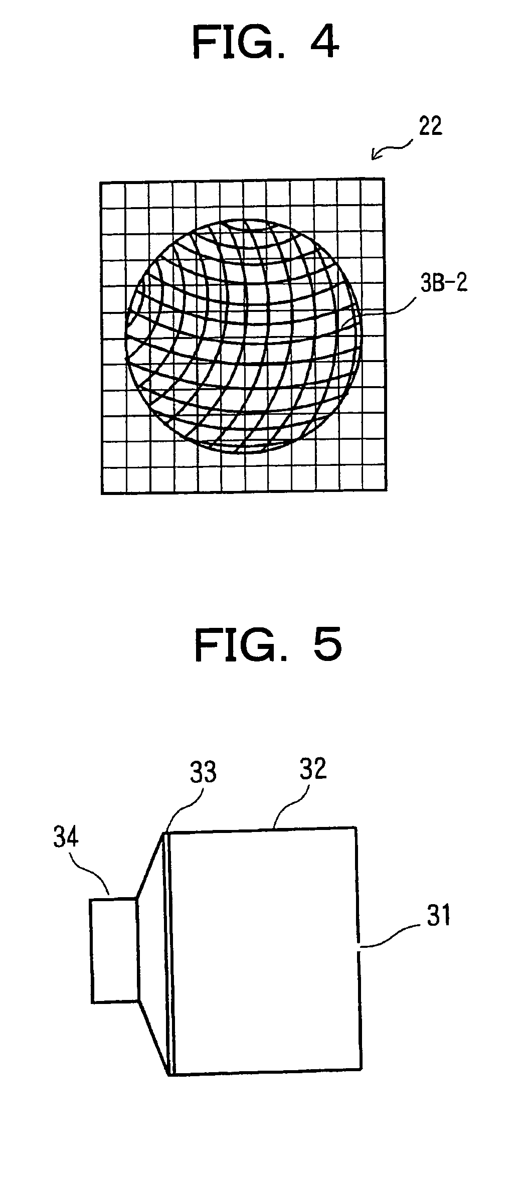
[0031]FIG. 3 is a schematic view of an image pick-up optical apparatus combining an opening and a CCD according to a second embodiment of the present invention. FIG. 4 is a schematic view illustrating image distortion caused by a spatial image-forming system and lens image-forming system using a calibration grid pattern of a wave-converting surface.

[0032]In these figures, an incident electromagnetic wave 5 is converted into visible light by the wave-c...


PUM


Abstract

An opening is made in a surface intercepting a wave propagating through space. An image of an object is formed on an intermediate surface from the wave passing through this opening. After wave conversion, that is to say, after the entity of a wave is converted into a detectable wave from which a two-dimensional image can be picked up, an image is picked up with a two-dimensional image pick-up device. Distortion caused by the two-dimensional image pick-up device is corrected using a calibration grid pattern provided on the intermediate surface. The intermediate surface provides a wave converting function, distortion calibrating function, distortion-free wide field of view ensuring function, and wave entity converting function, and a place of detection elements themselves.

Description

TECHNICAL FIELD[0001]The present invention relates to an apparatus including an opening made in a surface for intercepting a wave motion propagating through space. The apparatus forms an image of an object on an intermediate surface by a wave motion passing through the opening and picks up the image.BACKGROUND ART[0002]Hitherto, images of particular objects have been formed using light or other electromagnetic waves in various fields of science and technology. Image-forming systems using opening, which have been developed from the concept of a pinhole, are fundamental systems for such image formation. Light and other electromagnetic waves, which are examples of wave motion, have a characteristic that no distortion occurs in spatial projection.DISCLOSURE OF INVENTION[0003]In the present image-forming systems using an opening and having an interrupter that intercepts a wave motion, the opening being made in the interrupter, an image is formed geometrically due to rectilinear propagati...

Claims


Application Information

Patent Timeline
Patent Type & Authority Patents(United States)
IPC IPC(8): H04N5/225H04N5/30H04N5/217
CPCH04N5/217H04N23/81
Inventor YOSHIMURA, HIROKAZU
Owner JAPAN SCI & TECH CORP
Why Eureka
Try Eureka