Tunable filter and method of manufacturing the same, and sensing device

a filter and filter body technology, applied in the field of tunable filters, can solve the problems of easy variation of difficulty in arranging the length of the gap to be a desired value, and the possibility of sticking

Inactive Publication Date: 2007-11-27
SEIKO EPSON CORP
View PDF26 Cites 21 Cited by
  • Summary
  • Abstract
  • Description
  • Claims
  • Application Information

AI Technical Summary

Benefits of technology

[0011]An advantage of the invention is to provide a tunable filter that can be formed without removing the sacrifice layer and can separate light having a shorter wavelength than infrared light and a method of manufacturing the tunable filter, and a sensing device.
[0012]A tunable filter according to an aspect of the invention includes a fixed substrate provided with a fixed reflecting film and capable of transmitting light having a shorter wavelength than infrared light, a movable substrate provided with a movable section equipped with a movable reflecting film and disposed to the fixed substrate so that the movable reflecting film and the fixed reflecting film faces each other with a predetermined length of gap, and a drive section for varying the length of the gap by displacing the movable section with respect to the fixed substrate. Further, light entering the gap from the outside is repeatedly reflected by the movable reflecting film and the fixed reflecting film for outputting light having a wavelength corresponding to the length of the gap, and the movable section is provided, at an area to which the movable reflecting film is disposed, with a light transmitting section capable of transmitting light having a shorter wavelength than infrared light and for inputting / outputting light from / to the outside.
[0013]According to this, since the light transmitting section capable of transmitting light having a shorter wavelength than infrared light is provided, the wavelength separation of the light having a shorter wavelength than infrared light becomes possible.
[0014]A tunable filter according to another aspect of the invention includes a fixed substrate provided with a first hollow section and a second hollow section formed in one surface thereof, and capable of transmitting light having a shorter wavelength than infrared light, a movable substrate having a electrically conductive property and provided with a movable section and disposed to the fixed substrate so that the movable section faces bottom surfaces of the first and the second hollow sections, a movable reflecting film provided to a surface of the movable section, the surface facing the bottom surfaces of the first and the second hollow sections, a fixed reflecting film provided to the bottom surface of the first hollow section defining a first gap with the movable reflecting film, and a drive electrode provided to the bottom surface of the second hollow section defining a second gap with the movable section and for displacing the movable section with respect to the fixed substrate, by coulomb force generated by a potential difference from the movable section, to vary the length of the first gap. Further, light entering the first gap from the outside is repeatedly reflected by the movable reflecting film and the fixed reflecting film for outputting light having a wavelength corresponding to the length of the first gap, and the movable section is provided, at an area to which the movable reflecting film is disposed, with a light transmitting section capable of transmitting light having a shorter wavelength than infrared light and for inputting / outputting light from / to the outside.
[0015]According to this, since the light transmitting section capable of transmitting light having a shorter wavelength than infrared light is provided, the wavelength separation of the light having a shorter wavelength than infrared light becomes possible.
[0016]In the tunable filter, an insulating film may preferably be provided to at least one of an area of the movable section facing the drive electrode and an area of the drive electrode facing the movable section.

Problems solved by technology

Therefore, the length of the gap is determined by the thickness of the sacrifice layer, which causes a problem that the length of the gap is easy to be varied in accordance with the forming conditions of the sacrifice layer.
If the length of the gap is varied, the coulomb force generated in accordance with a predetermined applied voltage is varied, thus it becomes difficult to arrange the length of the gap to be a desired value.
However, since the movable mirror is not insulated from the drive electrode equipped with the fixed mirror, a phenomenon called sticking may occur, in which the movable mirror is adhered to the drive electrode by the coulomb force.
Therefore, since the area of the electrode on the movable mirror is reduced as much as the area of the release hole, the drive voltage needs to be set higher in order for generating predetermined coulomb force, thus increasing the power consumption.
Further, if the required length of the gap is small, the sticking caused by surface tension of water may occur in a cleaning process after removing the sacrifice layer.
Further, the filters disclosed in the above patent documents have problem that the light to be separated is limited to infrared light because silicon is provided to the light transmitting paths.

Method used


Image

  • Tunable filter and method of manufacturing the same, and sensing device
  • Tunable filter and method of manufacturing the same, and sensing device
  • Tunable filter and method of manufacturing the same, and sensing device

Examples


embodiment 1

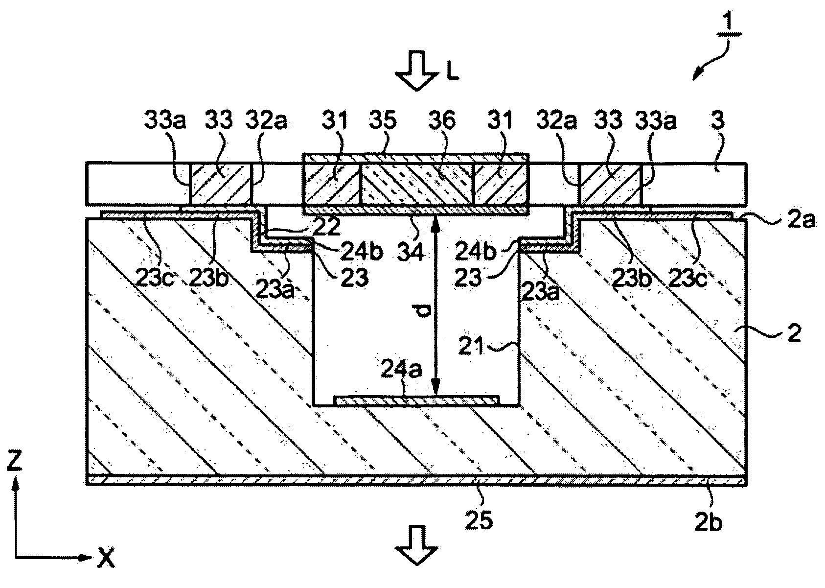
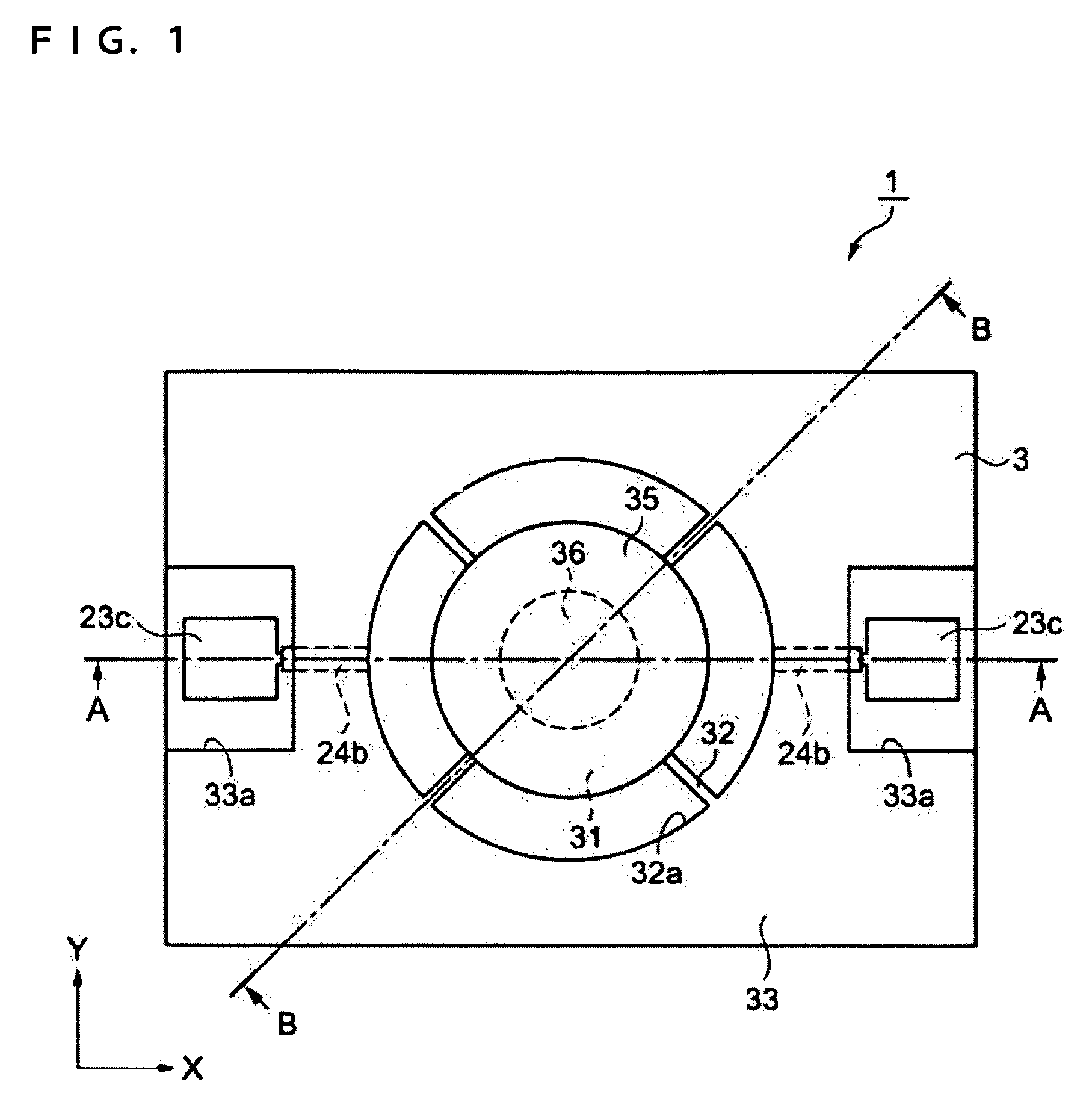
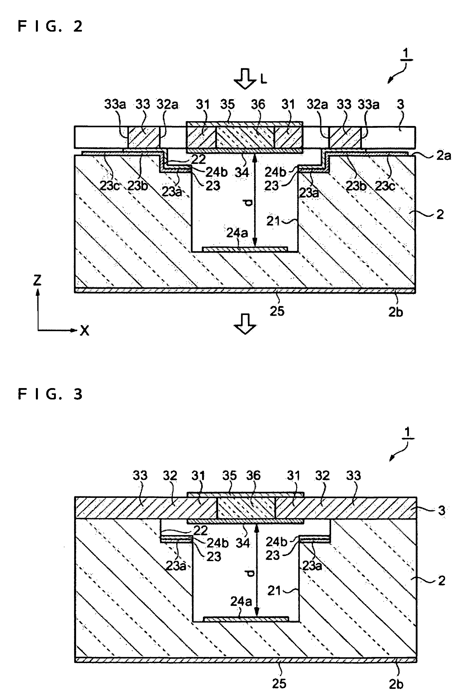
[0062]A tunable filter of a first embodiment according to the invention will now be described with reference to the accompanying drawings. FIG. 1 is a plan view showing the tunable filter of the present embodiment. FIG. 2 is a cross-sectional view thereof along the A—A line, and FIG. 3 is a cross-sectional view thereof along the B—B line.

[0063]As shown in FIGS. 1 through 3, the tunable filter 1 is equipped with a fixed substrate 2 and a movable substrate 3 bonded to the upper surface 2a of the fixed substrate 2.

[0064]The fixed substrate 2 is made of a material, having light transmittance property with respect to at least visible light, such as various kinds of glass. In the present embodiment, pyrex (registered trademark) glass #7740, sodium borosilicate glass produced by Corning Inc. is used therefor. The pyrex (registered trademark) glass, which contains sodium (Na) ions as mobile ions, is suitable for anodic bonding with the movable substrate 3 made of silicon, and further, since...

embodiment 2

[0120]The second embodiment of the invention will now be described with reference to the accompanying drawings. FIG. 12 is a configuration diagram of a sensing device equipped with the tunable filter 1 of the first embodiment.

[0121]As shown in FIG. 12, the sensing device 100 is equipped with a light inputting section 101, the tunable filter 1, and a sensing section 102. The light L input from the light inputting section 101 is wavelength-separated by the tunable filter 1, and only the light having a predetermined wavelength enters the sensing section 102.

[0122]According to the sensing device 100 of the present embodiment, since the tunable filter 1 is equipped with the light transmitting section 36 (See FIG. 2.) capable of transmitting the light having the shorter wavelength than infrared light, the sensing object for the sensing device 100 is not limited to infrared light.

modified embodiment

[0123]Note that the embodiments of the invention can be modified as follows.[0124]In the tunable filter 1 of the embodiment, although the light transmitting section 36 is formed to have substantially the same thickness as the movable substrate 3 (See FIG. 2.), the thickness of the light transmitting section 36 is not limited thereto, but can be thicker or thinner than the movable substrate 3.[0125]In the tunable filter 1 of the embodiment, although the fixed reflecting film 24a, the movable reflecting film 34, and the first and the second antireflection films 25, 35 are formed of the multilayer films, they can also be formed of single layer films.[0126]In the tunable filter 1 of the embodiment, although the drive section for driving the movable section 31 is configured so as to utilize the coulomb force, it can also be configured so as to utilize electromagnet force or a piezoelectric effect.[0127]In the method of manufacturing the tunable filter 1 of the embodiment, although the fi...


PUM

PropertyMeasurementUnit
thicknessaaaaaaaaaa
thicknessaaaaaaaaaa
thicknessaaaaaaaaaa

Abstract

A tunable filter including; a fixed substrate provided with a fixed reflecting film and capable of transmitting light having a shorter wavelength than infrared light; a movable substrate provided with a movable section equipped with a movable reflecting film and disposed to the fixed substrate so that the movable reflecting film and the fixed reflecting film faces each other with a predetermined length of gap; and a drive section for varying the length of the gap by displacing the movable section with respect to the fixed substrate, wherein light entering the gap from the outside is repeatedly reflected by the movable reflecting film and the fixed reflecting film for outputting light having a wavelength corresponding to the length of the gap, and the movable section is provided, at an area to which the movable reflecting film is disposed, with a light transmitting section capable of transmitting light having a shorter wavelength than infrared light and for inputting / outputting light from / to the outside.

Description

RELATED APPLICATIONS[0001]This application claims priority to Japanese Patent Application No. 2004-202739 filed Jul. 9, 2004 which is hereby expressly incorporated by reference herein in its entirety.BACKGROUND OF THE INVENTION[0002]1. Technical Field[0003]The present invention relates to a tunable filter capable of separating wavelengths of light and method of manufacturing the tunable filter, and a sensing device.[0004]2. Related Art[0005]When light is multiple-reflected between a pair of mirrors (reflecting films) facing each other with a predetermined length of the gap, only light with a specific wavelength corresponding to the length of the gap is transmitted (wavelength-separated). Tunable filters are capable of selecting a wavelength band of the light to be transmitted by tuning the length of the gap. Various kinds of filters having structures, realized by micro-machining, for varying the length of the gap using electrostatic force (coulomb force) generated in accordance with...

Claims


Application Information

Patent Timeline
Patent Type & Authority Patents(United States)
IPC IPC(8): G02B27/00G02B6/26
CPCG02B26/001G01J3/26G02B1/11G02B5/28
Inventor NAKAMURA, RYOSUKEMURATA, AKIHIRO
Owner SEIKO EPSON CORP
Why Eureka
Try Eureka