Road-milling machine or machine for working deposits

a technology of working deposits and milling machines, which is applied in the direction of cutting machines, roads, roads, etc., can solve the problems of reducing efficiency, affecting the efficiency of work, and affecting the surface on which work is to be done,

Active Publication Date: 2011-11-01
WIRTGEN GMBH
View PDF15 Cites 29 Cited by
  • Summary
  • Abstract
  • Description
  • Claims
  • Application Information

AI Technical Summary

Benefits of technology

[0009]The road-milling machine or machine for working deposits according to the invention is distinguished by the fact that the doing of work efficiently on a wide surface does not call for any preparatory measures such for example as the tensioning of a cord or the like. The machine according to the invention can be operated in the same way as the known working machines but allows the machine to be guided automatically so that the individual milled strips are situated exactly alongside one another.
[0020]In a further particularly preferred embodiment, the arrangement for detecting the path followed by the milled edge has first means for sensing the distance between a reference point which is preferably situated at the bottom end of the left-hand edge guard of the milling machine, and as a particular preference at the bottom front end of its left-hand edge guard, and second means for sensing the distance between a reference point which is preferably situated at the bottom end of the right-hand edge guard of the milling machine, and as a particular preference at the bottom front end of its right-hand edge guard, in which case the first or second means can be activated or de-activated as a function of the direction of travel of the road-milling machine. For further automation, means are provided for measuring the positions of the left-hand and right-hand edge guards. As a function of the direction of travel of the road-milling machine, one of the two edge guards rests on the surface which has already been milled, while the other edge guard rests on the surface which has not yet been worked on. The means for activating the first or second means for measuring the distance between the reference point and the milled edge co-operate with the means for measuring the positions of the right-hand and left-hand edge guards in such a way that those means for measuring distance are activated which are associated with the edge guard which is situated in the lower position, whereas the other means for determining distance, which are associated with the edge guard which is situated in the higher position, are de-activated. This ensures that the side on which the distance from the milled edge is determined is always that which is also being milled. There is thus no need for the driver of the machine to preset the side of the machine on which the distance is to be measured.

Problems solved by technology

When the machine is being used, the problem arises that the surfaces on which work is to be done are of a size whose width is a multiple of the working width of the machine.
Making this balance is a great strain on the driver and is tiring because, as well as the other jobs he has to do such as coordinating the unloading of the material picked up and doing the levelling, he also has to steer the machine exactly over the entire distance over which milling takes place.
The driver is always faced with a conflict in this case, in that drifting into the strip milled previously will reduce efficiency but drifting in the opposite direction will result in work not being done on the whole of the surface.
In the case of a milling machine which has an edge guard, there is also a risk of the machine being seriously damaged if the edge guard is pulled off.
It is true that the known road-milling machine allows the direction of travel to be controlled exactly but the need to have to tension a cord along the desired strip to be milled is found to be a disadvantage.

Method used


Image

  • Road-milling machine or machine for working deposits
  • Road-milling machine or machine for working deposits
  • Road-milling machine or machine for working deposits

Examples


Embodiment Construction

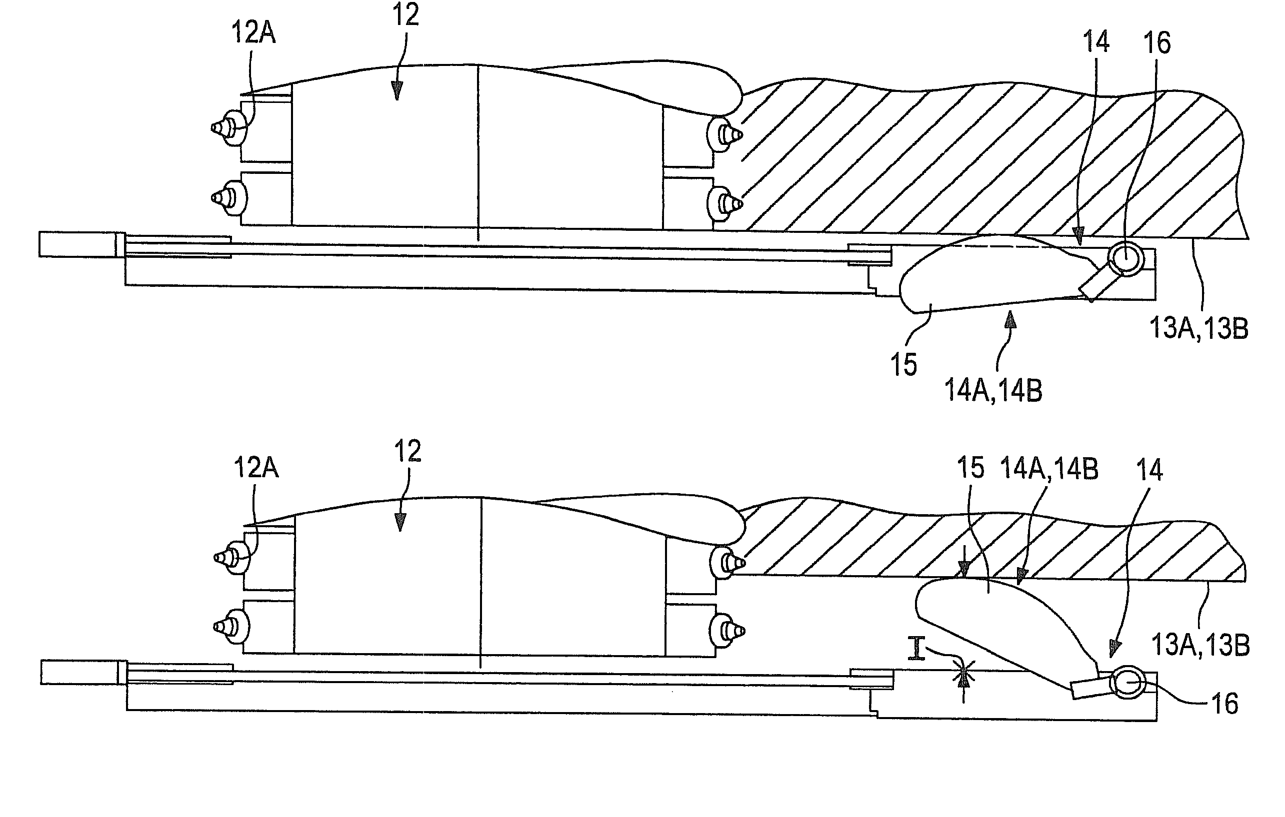
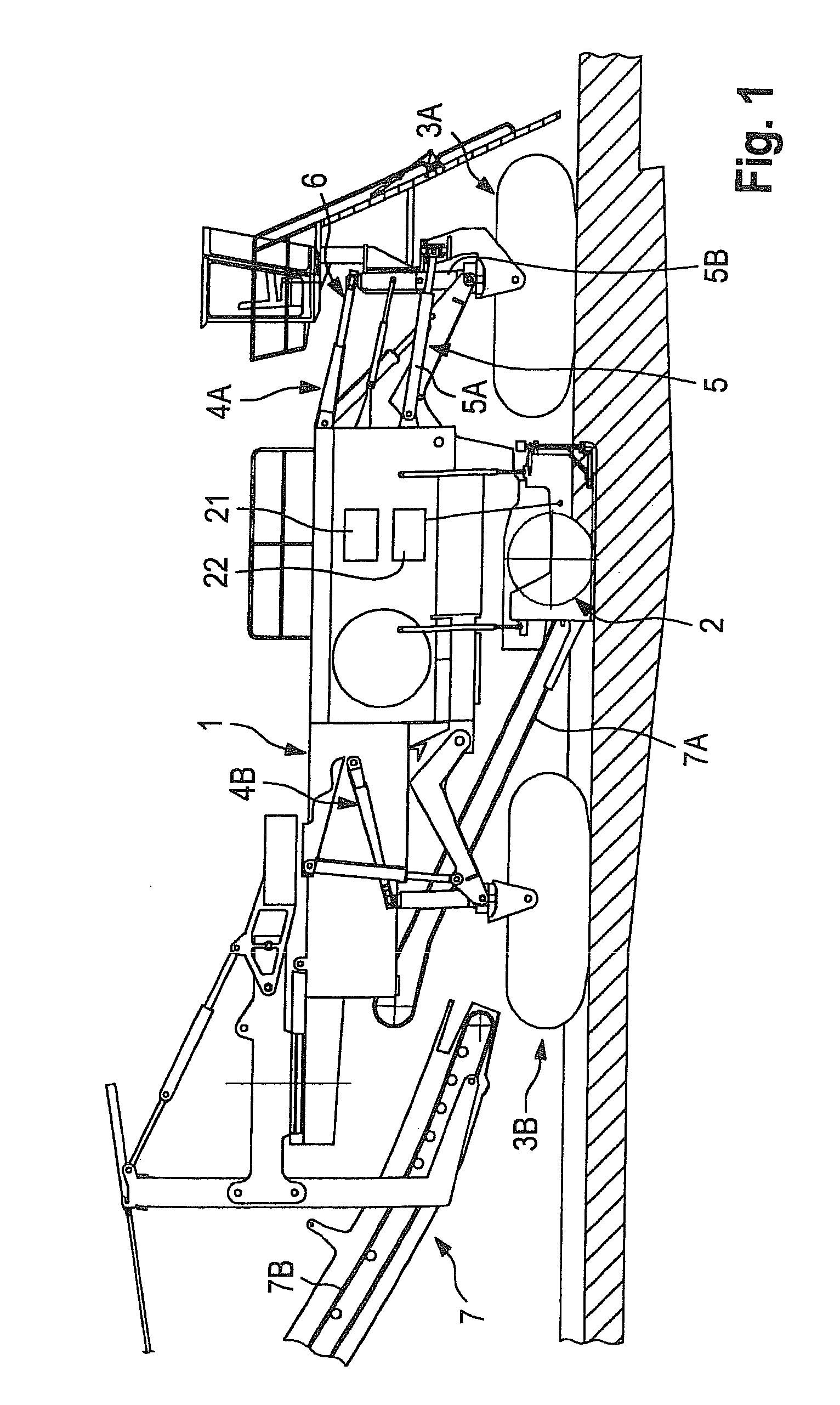
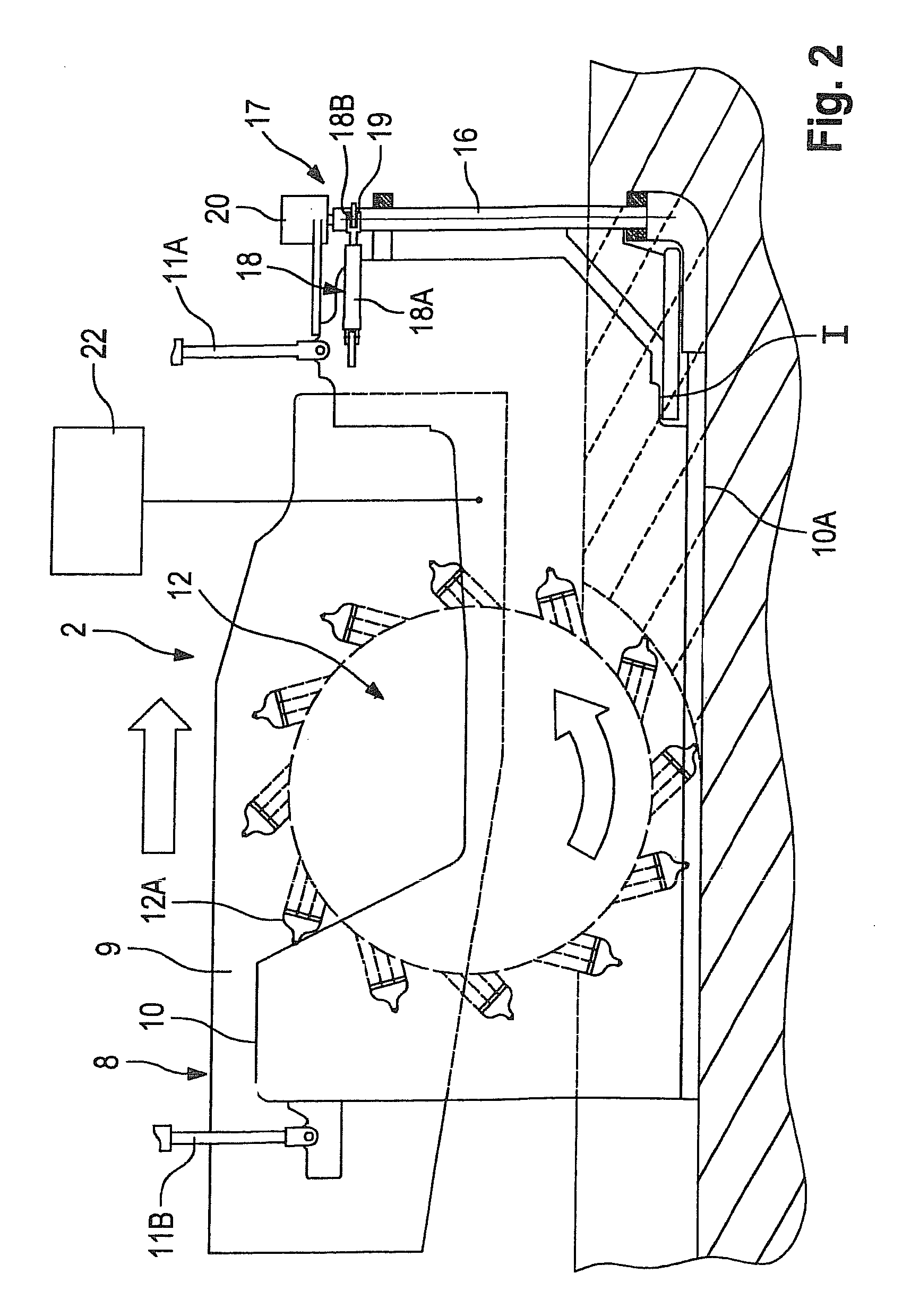
[0031]FIG. 1 is a view from the side showing a machine for working deposits by surface mining, which will be referred to in what follows as a surface miner. The construction and operation of a surface miner are familiar to the person skilled in the art and for this reason it will only be those components of the surface miner which are relevant for the purpose of allowing the invention to be understood that will be described in what follows. A road-milling machine, whose construction and operation are likewise familiar to the person skilled in the art, will not be described because it is only the milling arrangement and the steering arrangement which are relevant to the invention and these do not differ in any fundamental way from the milling and steering arrangements of a surface miner as far as the components relevant to the invention are concerned.

[0032]The surface miner for milling or cutting mineral matter has a chassis 1 which is formed by a welded structure stiff in bending. A...


PUM


Abstract

The invention relates to a road-milling machine or machine for working deposits, such as deposits of coal, ores, minerals, etc. by surface mining. The machine according to the invention has an arrangement 14 for detecting the path followed by a milled edge 13 of a milled strip, with the arrangement for detecting the path followed by the milled edge having means 14 for measuring the distance between at least one reference point I on the machine and the milled edge. The means 14 for detecting the path followed by the milled edge co-operate with the arrangement 6 for steering the track-laying units 3A, 3B in such a way that the machine follows the path followed by the milled edge. The distance between the at least one reference point on the machine and the milled edge can be set in such a way that milled strips situated alongside one another are exactly aligned relative to one another.

Description

FIELD OF INVENTION[0001]The invention relates to a road-milling machine or a machine for working deposits such for example as deposits of coal, ore, minerals, etc. by surface mining.BACKGROUND OF THE INVENTION[0002]There are various kinds of self-propelled machines for milling which are known. These machines include, in particular, road-milling machines, which can be used to remove existing layers of the surfacing structure of roads, and machines for working deposits by surface mining.[0003]Road-milling machines have a milling arrangement which has a mechanically or hydraulically driven milling drum. The machines for working deposits by surface mining, which are referred to as surface miners, also have a milling arrangement having a milling drum, which is also referred to as a cutting drum in the case of a surface miner. The milling drums of road-milling machines and surface miners are fitted with tool holders to receive the milling tools.[0004]The milling drums of road-milling mach...

Claims


Application Information

Patent Timeline
Patent Type & Authority Patents(United States)
IPC IPC(8): E01C23/07E01C23/08E01C23/16E21C25/00
CPCE01C19/004E01C23/088
Inventor VON SCHONEBECK, WINFRIEDHAHN, GUNTER
Owner WIRTGEN GMBH
Why Eureka
Try Eureka