
Systems and methods for controlling a converter for powering a load

a technology of system and method, applied in the field of power converters, can solve the problems of increasing the probability that any one individual component switch may randomly fail, increasing the number of components that can fail, and costing and extended outages

Active Publication Date: 2011-11-01
GENERAL ELECTRIC CO
View PDF9 Cites 22 Cited by
  • Summary
  • Abstract
  • Description
  • Claims
  • Application Information

AI Technical Summary

Benefits of technology

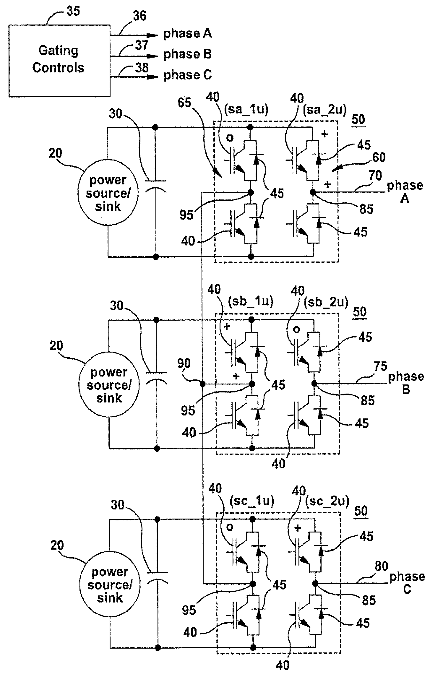
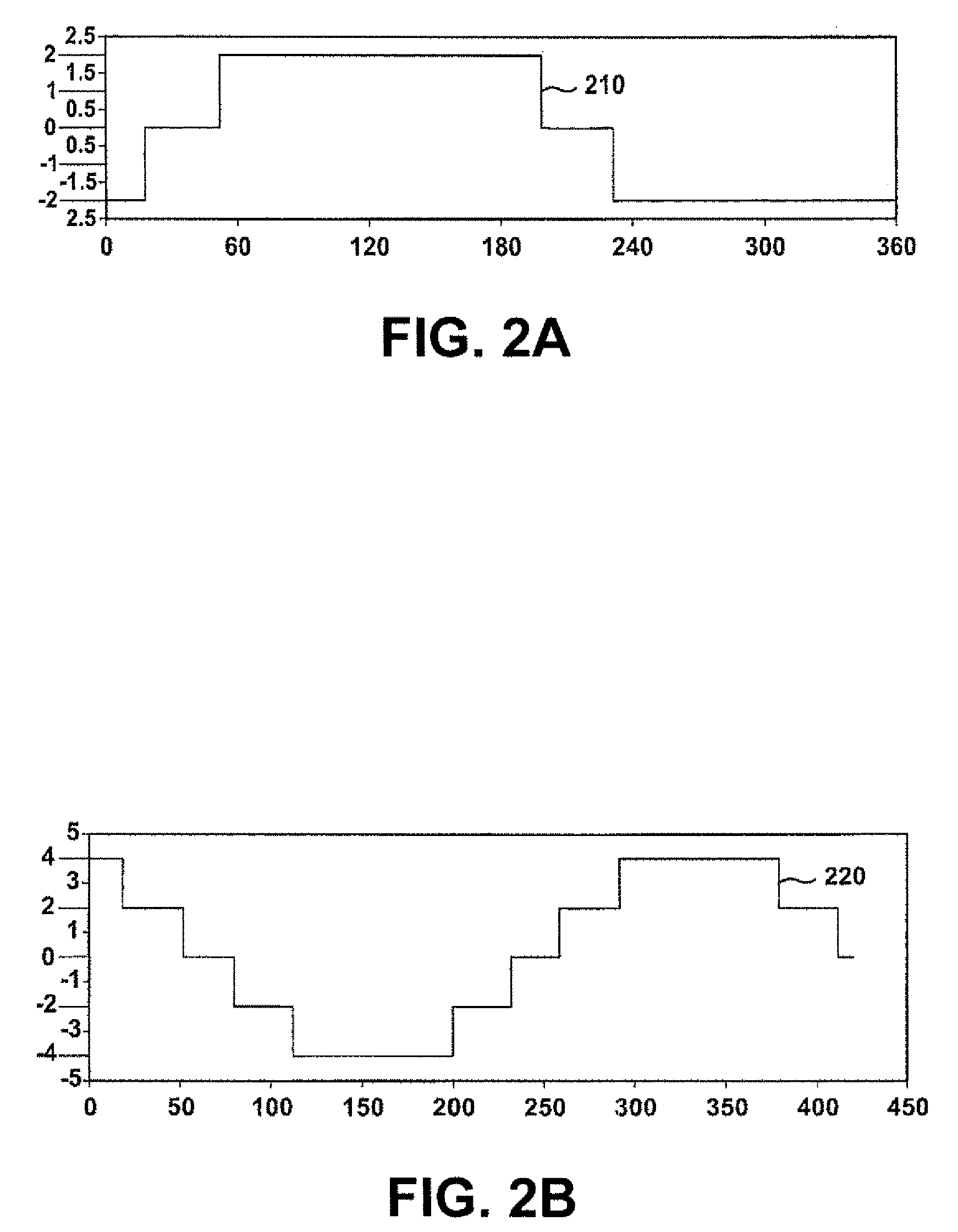
"The invention relates to a method and system for powering a load using a power converter. The method involves supplying a gating control signal with a switching pattern to the power converter, which has a waveform with an effective switching frequency greater than 1 times the fundamental frequency and less than 2 times the fundamental frequency. The power converter then outputs an output power signal to the load in response to the gating control signal. The system includes a voltage source, a converter, and a gating controller. The gating controller supplies the gating control signal to the converter, which converts the power signal to the output power signal. The technical effect of the invention is to improve the efficiency and accuracy of power conversion for loads."

Problems solved by technology

In operations such as crude oil pumping from remote global locations where access to pumping stations is difficult and time-consuming, reliability of motor operation may prevent dangerous, costly and extended outages.
It is well known that providing multiple individual components, such as series or parallel semiconductor switches, may increase the likelihood that any one individual component switch may randomly fail.
Added elements such as snubber circuits for semiconductor switches, further increases the number of components that can fail.
Reduction in switching loss will keep semiconductor H-bridge switches operating at lower temperatures with a greater margin to failure.

Method used


Image

  • Systems and methods for controlling a converter for powering a load
  • Systems and methods for controlling a converter for powering a load
  • Systems and methods for controlling a converter for powering a load

Examples


Embodiment Construction

Illustrative embodiments of the inventions now will be described more fully hereinafter with reference to the accompanying drawings, in which some, but not all embodiments of the inventions are shown. Indeed, these inventions may be embodied in many different forms and should not be construed as limited to the embodiments set forth herein; rather, these embodiments are provided so that this disclosure will satisfy applicable legal requirements. Like numbers refer to like elements throughout.

The following embodiments of the invention have many advantages, including providing adjusted switching waveforms and / or zero-current notch switching waveforms for large high-speed ac motors that provide current and voltage harmonics that are lower than prior art switching waveforms, while at the same time minimizing switching loss, thereby maximizing bridge output power capability.

The power factor of the motor determines the relationship between the converter output voltage and the load current....


PUM


Abstract

Systems and methods for controlling a converter for powering a load are provided. According to one embodiment of the invention, a method for powering a load is provided. A power converter may be provided. At least one gating control signal having a switching pattern may be supplied to the power converter, wherein the switching pattern has a waveform with an effective switching frequency greater than 1 times the fundamental frequency of the switching pattern and less than 2 times the fundamental frequency of the switching pattern. At least one output power signal may be output to the load responsive at least in part to the at least one gating control signal supplied.

Description

TECHNICAL FIELDThe invention relates generally to power converters, and more particularly relates to systems and methods for controlling a converter for powering a load.BACKGROUND OF THE INVENTIONHigh-speed, high-power electric motors that operate at variable speed are increasingly utilized in a range of industrial, mining and drilling activities. Further, the activities often depend upon a high-degree of reliability. In operations such as crude oil pumping from remote global locations where access to pumping stations is difficult and time-consuming, reliability of motor operation may prevent dangerous, costly and extended outages. Simple, sturdy and reliable power converters are preferred for such high-speed, high-power motor operations. It is well known that providing multiple individual components, such as series or parallel semiconductor switches, may increase the likelihood that any one individual component switch may randomly fail. Added elements such as snubber circuits for s...

Claims


Application Information

Patent Timeline
Patent Type & Authority Patents(United States)
IPC IPC(8): H02H7/122
CPCH02M7/48H02M7/483H02M7/53871H02P27/12H02P27/04H02P27/08H02P23/0086H02P23/28H02M1/08H02M5/458
Inventor WAGONER, ROBERT GREGORYRITTER, ALLEN
Owner GENERAL ELECTRIC CO
Learn More