Multi-channel digital wireless audio system

a wireless audio and multi-channel technology, applied in the direction of wireless commuication services, stereophonic circuit arrangements, loudspeaker enclosure positioning, etc., can solve the problem of gross distortion of sound imag

Active Publication Date: 2011-11-01
ELEVEN ENG
View PDF31 Cites 221 Cited by
  • Summary
  • Abstract
  • Description
  • Claims
  • Application Information

AI Technical Summary

Benefits of technology

[0020]Preferred embodiments of the invention enable the use of relatively inexpensive, narrow-band digital radios (such as those used in digital cordless telephones) while still achieving high QoS, by utilizing audio compression and decompression techniques to reduce data payload requirements. One embodiment uses a single radio transceiver on each node (to reduced cost and power consumption), while using digital techniques to create fidelity and QoS comparable to or better than the fidelity and QoS achieved by more expensive analog pro audio solutions. This embodiment may be used to implement high QoS to several remote speakers.
[0053]An alternative embodiment of the invention incorporates two or more transmit nodes and two or more receive nodes, with the system being adapted such that each receive node, upon being powered up, will bond with a selected transmit node, and each receive node comprises bond rejection means which may be activated to reject the bond with the selected transmit node and to cause the receive node to bond to the next available transmit node, thus enabling a user to select a desired audio source.

Problems solved by technology

These typically overlap with VHF and UHF TV channels, forcing users to determine whether or not there is a conflict in each city.
For example, without precise synchronization between left and right channels of a stereo signal, the sound image will be grossly distorted.
The challenge comes in implementing the general case in which fidelity and QoS must be maintained at or above desired minimum levels while end-to-end system latency is kept to at or below a desired maximum level.
There are other global considerations such as system size, cost, and power consumption that typically have hard constraints in practical embodiments.

Method used


Image

  • Multi-channel digital wireless audio system
  • Multi-channel digital wireless audio system
  • Multi-channel digital wireless audio system

Examples


Embodiment Construction

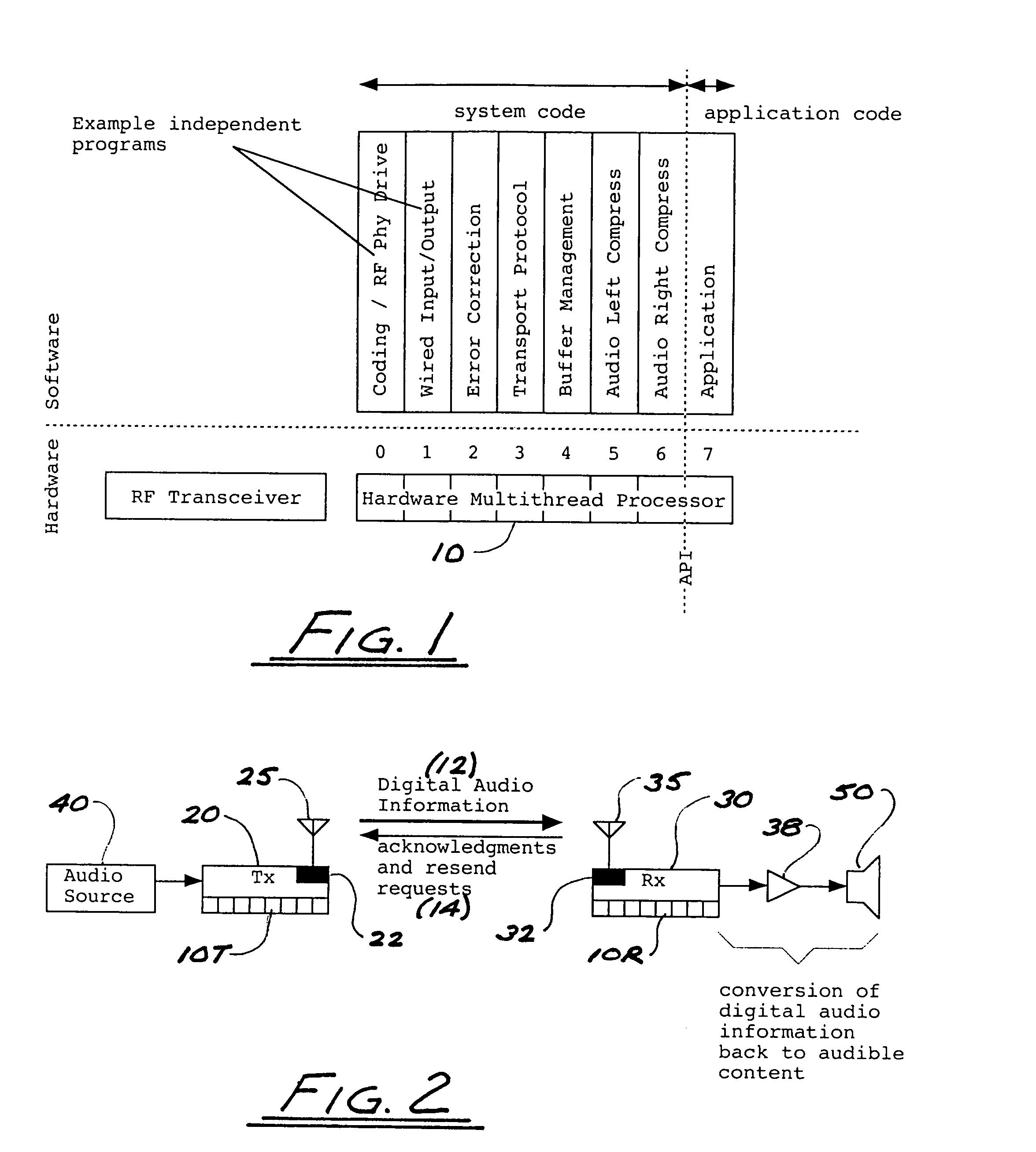
[0082]FIG. 1 schematically illustrates a hardware-multithreaded processor 10 of a general type suitable for use in association with preferred embodiments of the present invention. Further information regarding suitable hardware-multithreaded processors is disclosed in the commonly-owned U.S. patent application Ser. No. 09 / 843,178, which application is hereby incorporated herein by reference in its entirety. In the exemplary processor 10 shown in FIG. 1, eight separate software programs can be run on a single hardware-multithreaded processor, simultaneously enabling multiple functional blocks in software. Since the multithreading is hardware-based, the software programs do not interfere with one another through hardware loading; i.e., they run independently, and a change in the audio compression algorithm will not affect the sensitive timing of the protocol, for example.

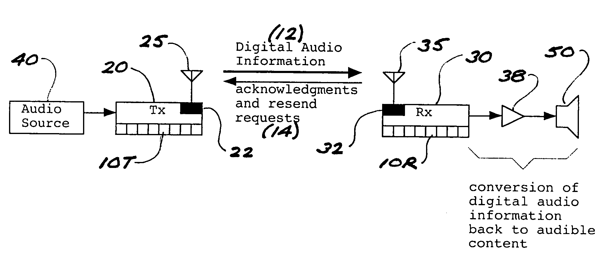
[0083]FIG. 2 illustrates an embodiment of the present invention in which a transmit node 20 is engaged with a recei...


PUM


Abstract

In a multi-channel digital wireless audio system with at least one transmit node and at least one receive node, each node can both receive and transmit digital audio signals. Signals sent from a receive node to a transmit node may acknowledge satisfactory signal receipt, or may requesting retransmission of data packets received in a corrupted state. Original and retransmitted signals may be sent in compressed form to enable use of narrow-band digital radios. The system preferably incorporates a dual control channel to enable transmission of meta data. Each system node preferably incorporates a hardware-multithreaded processor adapted to implement various functions such as baseband functions, RF protocol functions, error correction functions, and audio processing functions, with each independent thread being adapted to implement a different functional block.

Description

CROSS-REFERENCE TO RELATED APPLICATIONS[0001]This application claims the benefit, pursuant to 35 U.S.C. 119(e), of U.S. Provisional Application No. 60 / 637,772, filed on Dec. 22, 2004, and said provisional application is hereby incorporated herein by reference in its entirety.FIELD OF THE INVENTION[0002]The present invention relates to wireless audio systems, and in particular to digital wireless audio systems in which system latency is configurable within a selected range.TERMINOLOGY[0003]Terms, acronyms, and abbreviations appearing in the Glossary section of this patent document are intended to be understood in accordance with the definitions or explanations set out in the Glossary, unless the context clearly requires otherwise. Terms not appearing in the Glossary or otherwise defined in this specification are intended to have the meanings generally understood by persons skilled in the art of the invention.[0004]In this document, the word “comprising” is used in its non-limiting se...

Claims


Application Information

Patent Timeline
Patent Type & Authority Patents(United States)
IPC IPC(8): H04B7/00
CPCH04L1/1829H04R5/04H04R2205/024H04R2420/07
Inventor JACOBSEN, PHILLIPSOBOTA, JOHNNORTHCOTT, RYANQUALIE, JIMFISHER, PATRICKGOSIOR, JASON
Owner ELEVEN ENG
Why Eureka
Try Eureka