
Temperature measuring circuit in a flowmeter

a technology of temperature measurement circuit and flowmeter, which is applied in the direction of heat measurement, volume metering, instruments, etc., can solve the problems of large individual differences among the circuits, poor temperature characteristics of the circuit, and large measurement errors, etc., to suppress the addition of the number of components, wide measurement temperature range, and suppress the effect of measurement error

Active Publication Date: 2011-11-08
OVAL CORP
View PDF7 Cites 0 Cited by
  • Summary
  • Abstract
  • Description
  • Claims
  • Application Information

AI Technical Summary

Benefits of technology

[0014]The present invention has been made in view of the above-mentioned circumstances, and it is an object of the present invention to provide a temperature measuring circuit in the flowmeter, which is capable of reducing the number of components, and of reducing the effect of characteristic changes of the components, which are caused by the individual difference among the components and by the temperature of the components.
[0016]According to the present invention having such a feature as described above, the components other than the reference resistor are not affected by the temperature or the individual difference. Further, according to the present invention, even if measured voltages are changed in measurement of the divided voltages, the changes of the measured voltages do not affect measurement of the resistance if the voltage ratio is correct. Still further, according to the present invention, constituent elements (components) of the circuit are reduced.
[0018]According to the present invention having such a feature as described above, it becomes possible to suppress the measurement error in a wide measurement temperature range to be extremely low. By applying a hyperbolic approximate expression (Y=1 / X), it becomes possible to suppress addition to the number of components.
[0019]According to the present invention, there are exerted an effect that the temperature measuring circuit is capable of reducing the number of components, and of reducing the effect of the characteristic changes of the components, which are caused by the individual difference among the components and by the temperature of the components.

Problems solved by technology

A first problem is that temperature characteristics of the circuit are not good.
This is because, when temperature characteristics of components other than the reference resistor 5 are changed by an influence from the ambient temperature and the like, a large measurement error is caused thereby.
A second problem is that an individual difference among the circuits becomes large because the number of components is large.
Besides, the circuit combines a secondary drawback that attention must be paid to calibration for adjusting the individual difference, and the like.
A third problem is that components must be further added to the circuit in the case of performing the measurement while providing a plurality of temperature measuring positions of a sensor (while providing two or more circuits).
Therefore, it becomes impossible to ignore complicated influences on the performance and the temperature change.

Method used


Image

  • Temperature measuring circuit in a flowmeter
  • Temperature measuring circuit in a flowmeter
  • Temperature measuring circuit in a flowmeter

Examples


Embodiment Construction

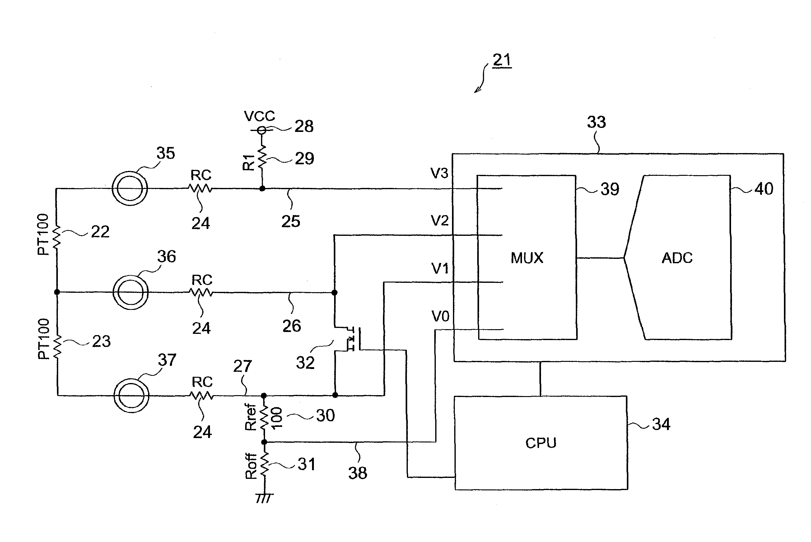
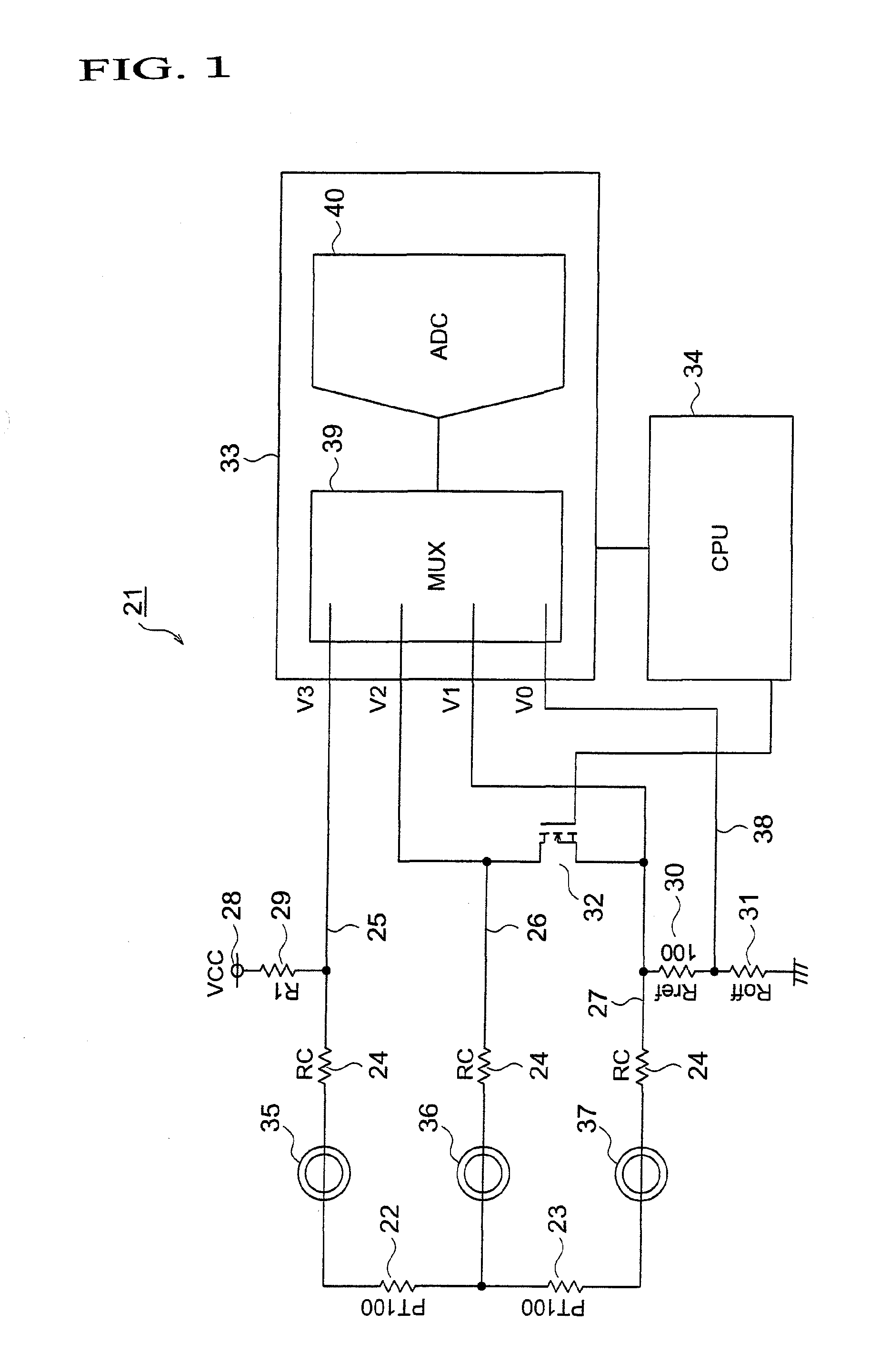
[0026]While referring to the drawings, a description is made below. FIG. 1 is a basic configuration diagram illustrating an embodiment of a temperature measuring circuit in a flowmeter of the present invention.

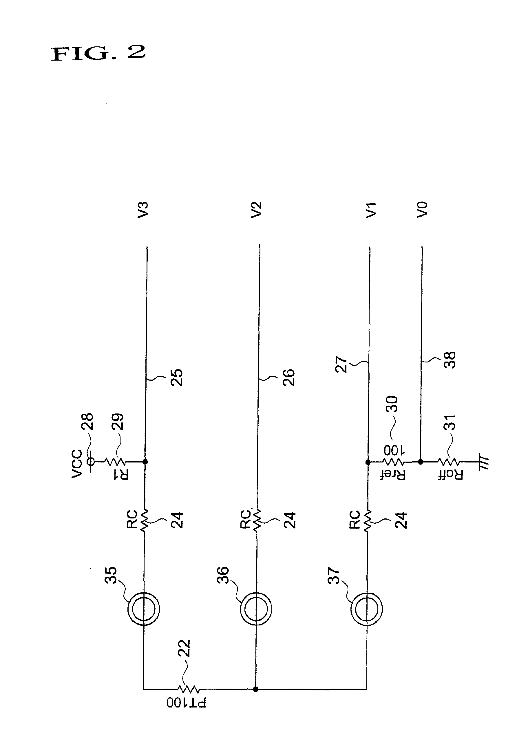
[0027]In FIG. 1, reference numeral 21 denotes the temperature measuring circuit. The temperature measuring circuit 21 is provided as a constituent of a Coriolis flowmeter (not shown). The temperature measuring circuit 21 is constructed by including: a first resistor-type temperature sensor 22 (PT100: 100Ω); a second resistor-type temperature sensor 23 (PT100: 100Ω); a first electric wire 25 having a line-to-line resistor 24 (RC); a second electric wire 26 having a line-to-line resistor 24 (RC) in the same way; a third electric wire 27 having a line-to-line resistor 24 (RC) in the same way; a voltage reference 28 (VCC); a power supply resistor 29 (R1); a reference resistor 30 (Rref: 100Ω); an offset resistor 31 (Roff); an FET 32 (switching device); a multiplexer-added A / D conve...


PUM


Abstract

A value of a line-to-line resistor (24) is determined by subtracting a resistance value determined as a product of a voltage ratio based on divided voltages and a value of a reference resistor in a non-conductive state between a second electric wire (26) and a third electric wire (27) from a resistance value determined as a product of a voltage ratio based on the divided voltages and the value of the reference resistor in a conductive state therebetween. Once the value of the line-to-line resistor (24) is determined, it becomes possible to determine a compensated resistance value related to temperature.

Description

TECHNICAL FIELD[0001]The present invention relates to a temperature measuring circuit in a flowmeter.BACKGROUND ART[0002]A Coriolis flowmeter is a mass flowmeter that supports both ends of a measuring tube through which a fluid to be measured flows, and detects a phase difference signal proportional to a mass flow rate at symmetric positions between both-end supported portions and a center portion of the thus supported measuring tube at a time when the center portion of the supported measuring tube is alternately driven in a direction perpendicular to a line of support. The measuring tube is formed of a metal material having a Young's modulus that changes with a temperature. Hence, in order to maintain high measurement accuracy, it is necessary to measure the temperature of the measuring tube, and to compensate for the change of the Young's modulus, which follows a change of the temperature.[0003]A description is made below of the temperature measurement using the Coriolis flowmeter...

Claims


Application Information

Patent Timeline
Patent Type & Authority Patents(United States)
IPC IPC(8): G01F1/69
CPCG01F1/8431G01F1/8436G01F15/024G01K7/21G01K13/02G01K1/026G01K7/206G01F1/84G01F1/86G01F25/00
Inventor SHIMADA, HIDEKI
Owner OVAL CORP
Learn More