
Worm gear drive

a gear drive and gear technology, applied in the direction of toothed gearings, belts/chains/gearings, gear details, etc., can solve the problems of reducing the efficiency of the gear drive, unable to back drive the motor, and unable to achieve the effect of reducing the cost of operation, and ensuring the effect of operation

Inactive Publication Date: 2011-11-08
JOHNSON ELECTRIC SA
View PDF15 Cites 10 Cited by
  • Summary
  • Abstract
  • Description
  • Claims
  • Application Information

AI Technical Summary

Benefits of technology

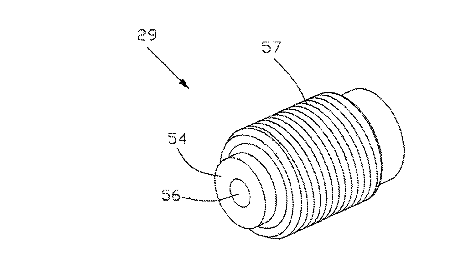
[0010]The present invention provides a self locking worm gear drive which has a simple and efficient structure. The invention removes the locking feature from the gear interface, allowing the gears to be designed for maximum efficiency or at least better matched to the application and adds the self lock feature to the thrust bearing interface. This is achieved by increasing the friction between the end of the motor shaft, and one or both of the thrust bearing plates. The preferred method of achieving this increased friction is by providing a recess in the surface of the thrust bearing so that the contact between the shaft end and the thrust surface is shifted from the axis of the shaft.

Problems solved by technology

There is a certain loss of power due to friction between the worm and the worm wheel.
By making certain modifications, this friction can lead to an arrangement where the load cannot back drive the motor due to the losses in the gears.
However, both of these measures decrease the efficiency of the gear drive resulting in the need for a more powerful motor to drive the load.
These designs have a separate braking or clutch mechanism to prevent back drive but these mechanisms are usually complex, prone to failure and add weight and cost to the final assembly.

Method used


Image

  • Worm gear drive
  • Worm gear drive
  • Worm gear drive

Examples


Embodiment Construction

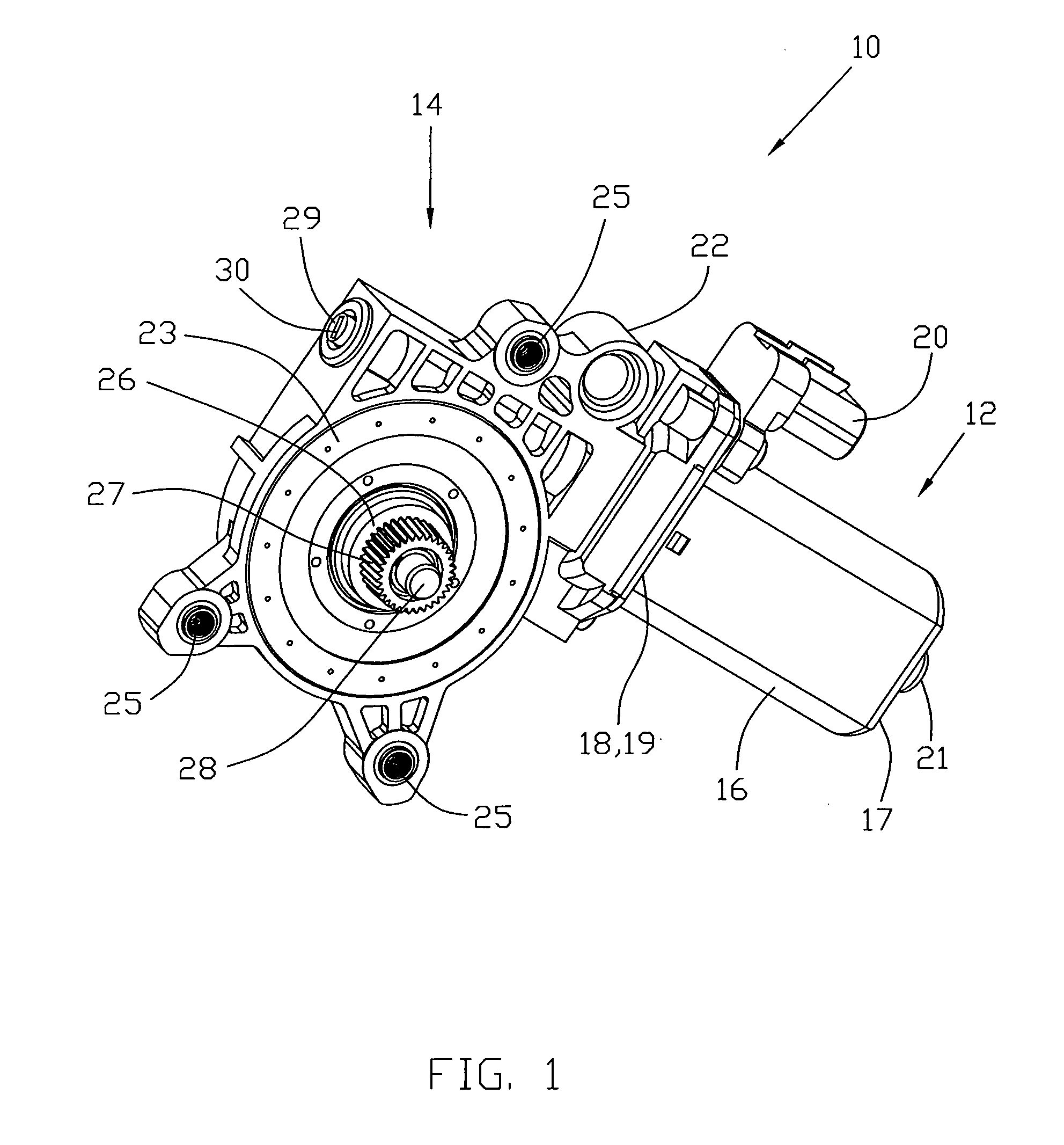
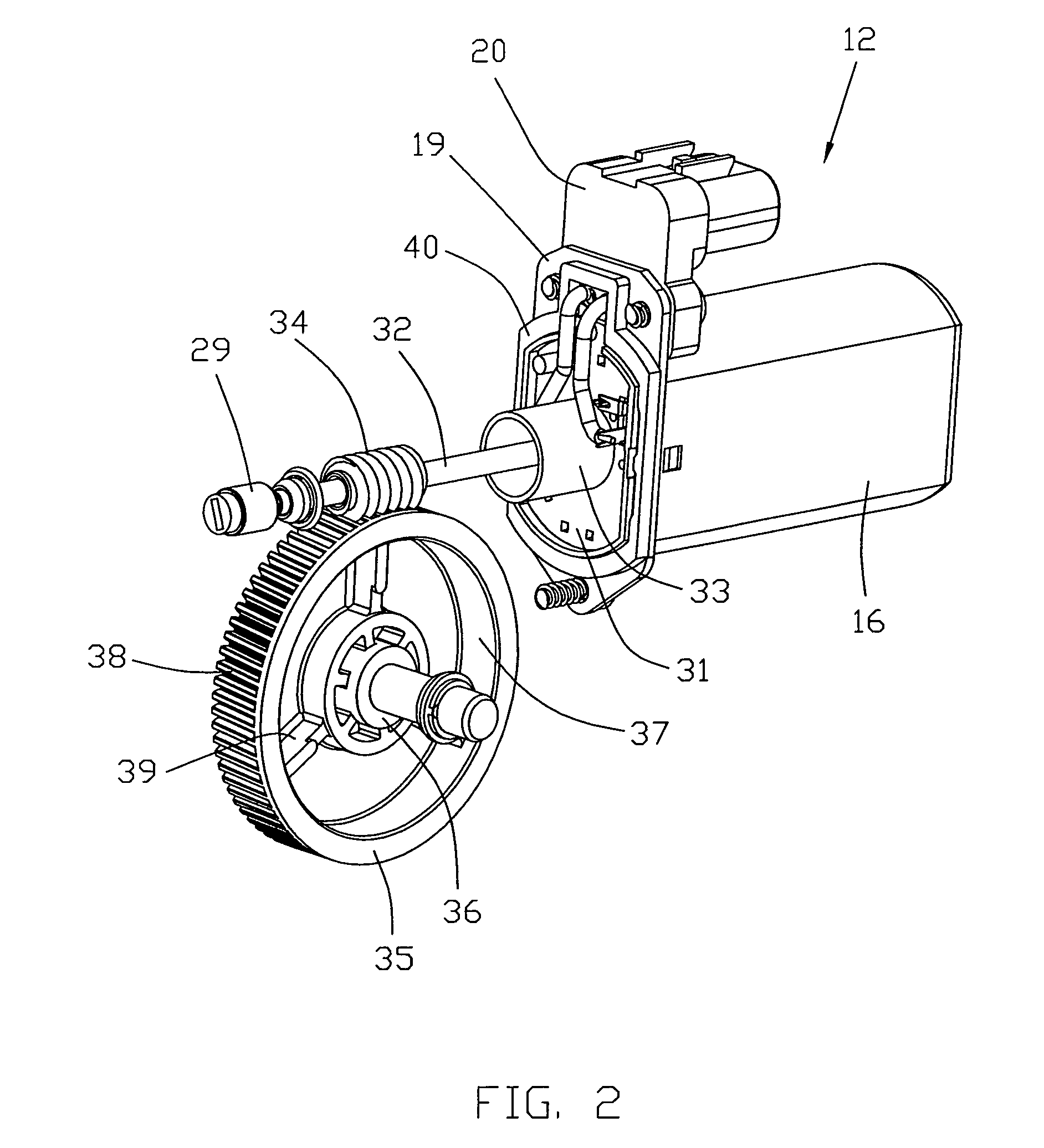
[0036]The apparatus of FIG. 1 is a worm gear drive 10 according to the preferred embodiment of the present invention. The drive comprises a motor 12 and a gearbox 14. The motor is bolted directly to the gearbox. This drive is used for moving a window in a passenger vehicle and is of the type commonly referred to as a window lift motor.

[0037]The motor 12 is a PMDC motor having a deep drawn steel housing 16 having a closed lower end 17 and an open upper end 18. The open end has a flange 19 for mounting an electrical connector 20 and the gearbox 14. A bearing retainer or boss 21 is formed in the closed end 17 for mounting a thrust bearing and a shaft bearing.

[0038]The gearbox 14 has a gearbox housing 22 accommodating the gear train. The gearbox housing 22 includes a lid 23 for closing the gearbox. The gearbox housing has three mounting holes 25 for mounting the drive to a support bracket in the door of a vehicle. The lid 23 is shown fixed to the gearbox housing 22.

[0039]Extending throu...


PUM


Abstract

A worm gear drive has a self locking gear train. The gear train comprises a worm 34 fitted to a motor shaft 32 and in mesh with a worm wheel 35 which drives the output 26. The motor shaft 32 extends between two thrust bearings 29, 60 having faces 54 which contact respective axial ends of the motor shaft 32. The contact between at least one of the thrust bearings 29 and the shaft 32 is adapted to provide a high frictional force.

Description

CROSS-REFERENCE TO RELATED APPLICATIONS[0001]This non-provisional patent application claims priority under 35 U.S.C. §119(a) from Patent Application No. 200610146490.1 filed in China on 11 Oct. 2006.FIELD OF THE INVENTION[0002]This invention relates to worm gear drives and in particular to a self locking worm gear drive.BACKGROUND OF THE INVENTION[0003]Worm gear drives comprise a worm or helical cog driven by a shaft and in mesh with a worm wheel driving an output, typically a shaft or cog. Worm gear drives are speed step down gearboxes and as such increase the torque developed by the motor driving the shaft. Usually, the driving shaft is the motor shaft and the worm is fitted to the shaft or formed on the shaft.[0004]In certain applications the use of a worm gear drive is desirable due to the simplicity of construction and because of the torque able to be delivered because of the gear ratio. There is a certain loss of power due to friction between the worm and the worm wheel. By ma...

Claims


Application Information

Patent Timeline
Patent Type & Authority Patents(United States)
IPC IPC(8): F16H1/16
CPCF16H1/16F16H57/039Y10T74/19828F16H2057/125F16H2057/0213F16H2057/0221
Inventor LI, FENGTA, JING NING
Owner JOHNSON ELECTRIC SA
Learn More