Rotary drill bits with gage pads having improved steerability and reduced wear

a rotary drill bit and gage pad technology, applied in the field of rotary drill bits, can solve the problems of reducing the lateral stability of the associated rotary drill bit relative to the longitudinal axis extending through the wellbore formed by and achieve the effect of reducing wear and erosion, improving the steerability of the associated rotary drill bit, and maintaining the desired lateral stability of the rotary drill bi

Active Publication Date: 2011-11-08
HALLIBURTON ENERGY SERVICES INC
View PDF28 Cites 11 Cited by
  • Summary
  • Abstract
  • Description
  • Claims
  • Application Information

AI Technical Summary

Benefits of technology

[0008]In accordance with teachings of the present disclosure, a rotary drill bit may be formed with a plurality of blades having a respective gage portion or gage pad disposed on each blade. At least one gage pad may have an exterior tapered portion and / or an exterior recessed portion incorporating teachings of the present disclosure. Gage pads designed in accordance with teachings of the present disclosure may experience reduced wear and erosion while forming a wellbore, particularly non-vertical and non-straight wellbores.
[0009]Gage pads incorporating teachings of the present disclosure may improve steerability of an associated rotary drill bit while maintaining desired lateral stability of the rotary drill bit. Gage pads incorporating teachings of the present disclosure may also improve the ability of an associated rotary drill bit to form a wellbore with a more uniform inside diameter. A rotary drill bit formed in accordance with teachings of the present disclosure may often form a wellbore having a relatively uniform inside diameter which may generally correspond with an associated nominal diameter of the rotary drill bit. One aspect of the present disclosure may include designing rotary drill bits in accordance with teachings of the present disclosure having respective gage pads disposed on blades of a fixed cutter rotary drill bit or support arms of a roller cone drill bit to optimize downhole drilling performance. For some applications such gage pads may have exterior configurations which cooperate with other features of the associated rotary drill bit to improve steerability, particularly during formation of non-vertical or non-straight wellbores without sacrificing lateral stability of the rotary drill bit. For other applications such gage pads may improve ability of an associated rotary drill bit to ream a wellbore or form a wellbore with a more uniform inside diameter, particularly during formation of a non-vertical or non-straight wellbore.

Problems solved by technology

However, lateral stability of an associated rotary drill bit relative to a longitudinal axis extending through a wellbore being formed by the rotary drill bit may be reduced.

Method used


Image

  • Rotary drill bits with gage pads having improved steerability and reduced wear
  • Rotary drill bits with gage pads having improved steerability and reduced wear
  • Rotary drill bits with gage pads having improved steerability and reduced wear

Examples


Embodiment Construction

[0051]Preferred embodiments of the disclosure and its advantages are best understood by reference to FIGS. 1-12F wherein like number refer to same and like parts.

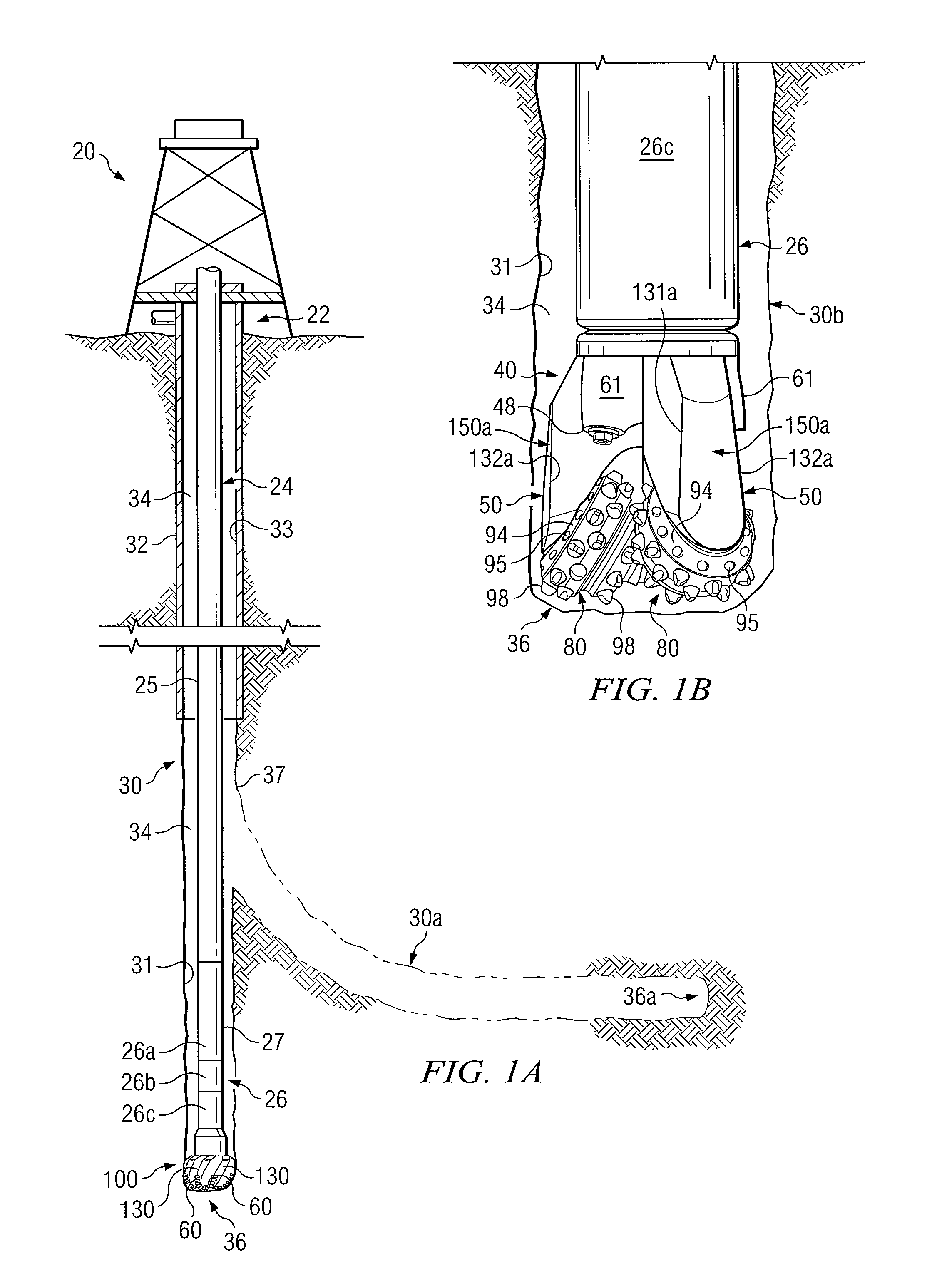
[0052]The term “bottom hole assembly” or “BHA” be used in this application to describe various components and assemblies disposed proximate a rotary drill bit at the downhole end of a drill string. Examples of components and assemblies (not expressly shown) which may be included in a bottom hole assembly or BHA include, but are not limited to, a bent sub, a downhole drilling motor, a near bit reamer, stabilizers and downhole instruments. A bottom hole assembly may also include various types of well logging tools (not expressly shown) and other downhole tools associated with directional drilling of a wellbore. Examples of such logging tools and / or directional drilling tools may include, but are not limited to, acoustic, neutron, gamma ray, density, photoelectric, nuclear magnetic resonance, rotary steering tools and / or any o...


PUM

PropertyMeasurementUnit
widthaaaaaaaaaa
widthaaaaaaaaaa
widthaaaaaaaaaa

Abstract

A rotary drill bit having blades with gage pads disposed on exterior portions thereof to improve steerability of the rotary drill bit during formation of a directional wellbore without sacrifice of lateral stability. One or more of the gage pads may include radially tapered exterior portions and / or cut out portions to assist with reducing wear of the associated gage pad. For some applications, a rotary drill bit may be formed having blades with gage pads having a relatively uniform exterior surface. Hard facing material and / or buttons may be disposed on exterior portions of the gage pad to form a radially tapered portion to improve steerability, reduce wear of the gage pad and / or improve ability of the rotary drill to form a wellbore having a generally uniform inside diameter, particularly during directional drilling of the wellbore.

Description

CROSS REFERENCE TO RELATED APPLICATIONS[0001]This application is a U.S. National Stage Application of International Application No. PCT / US2008 / 064862 filed May 27, 2008, which designates the United States of America, and claims the benefit of U.S. Provisional Patent Application No. 60 / 940,906, filed May 30, 2007. The contents of which are hereby incorporated herein in their entirety by this reference.TECHNICAL FIELD[0002]The present disclosure is related to rotary drill bits and particularly to fixed cutter drill bits having blades with cutting elements and gage pads disposed therein and also roller cone drill bits.BACKGROUND OF THE DISCLOSURE[0003]Various types of rotary drill bits, reamers, stabilizers and other downhole tools may be used to form a borehole in the earth. Examples of such rotary drill bits include, but are not limited to, fixed cutter drill bits, drag bits, PDC drill bits, matrix drill bits, roller cone drill bits, rotary cone drill bits and rock bits used in drill...

Claims


Application Information

Patent Timeline
Patent Type & Authority Patents(United States)
IPC IPC(8): E21B10/42
CPCE21B17/1092Y10T29/49
Inventor CHEN, SHILINASHLIE, RIUN
Owner HALLIBURTON ENERGY SERVICES INC
Why Eureka
Try Eureka