
Controllable or selectable bi-directional overrunning coupling assembly

a coupling assembly and bi-directional technology, applied in the direction of clutches, friction clutches, clutches, etc., can solve the problems of large quantity of lubricating fluid or oil, control plate or element use, etc., and achieve the effect of improving controllable or selectable overrunning coupling assemblies

Active Publication Date: 2011-11-08
MEANS IND INC
View PDF28 Cites 102 Cited by
  • Summary
  • Abstract
  • Description
  • Claims
  • Application Information

AI Technical Summary

Benefits of technology

The present invention provides an improved overrunning coupling assembly and clutch that can be controlled to selectively engage or disengage in opposite directions. The assembly includes first and second annular coupling members that support each other for relative rotation about a common rotational axis. The coupling members have annular coupling faces that oppose each other. The coupling face of the first coupling member has a first set of pockets with pivotal reverse struts received therein. The coupling face of the second coupling member has a second set of pockets with pivotal forward struts received therein. The assembly also includes a control element mounted for controlled, shifting movement between the coupling faces relative to the first set of pockets and operable for controlling the position of only the reverse struts without controlling the position of the forward struts. The control element allows at least one of the reverse struts to engage at least one of the second set of locking formations in a first position of the control element and maintain the reverse struts in their pockets in a second position of the control element. The assembly and clutch provide improved performance and control over the engagement and disengagement of the coupling members.

Problems solved by technology

One problem associated with the prior art selectable or controllable one-way clutches, is that a control plate or element is used to contain or control both forward and reverse struts in a stationary pocket plate.
Consequently, a relatively large quantity of lubricating fluid or oil is required to dampen the forward struts during overrun.

Method used


Image

  • Controllable or selectable bi-directional overrunning coupling assembly
  • Controllable or selectable bi-directional overrunning coupling assembly
  • Controllable or selectable bi-directional overrunning coupling assembly

Examples


Embodiment Construction

)

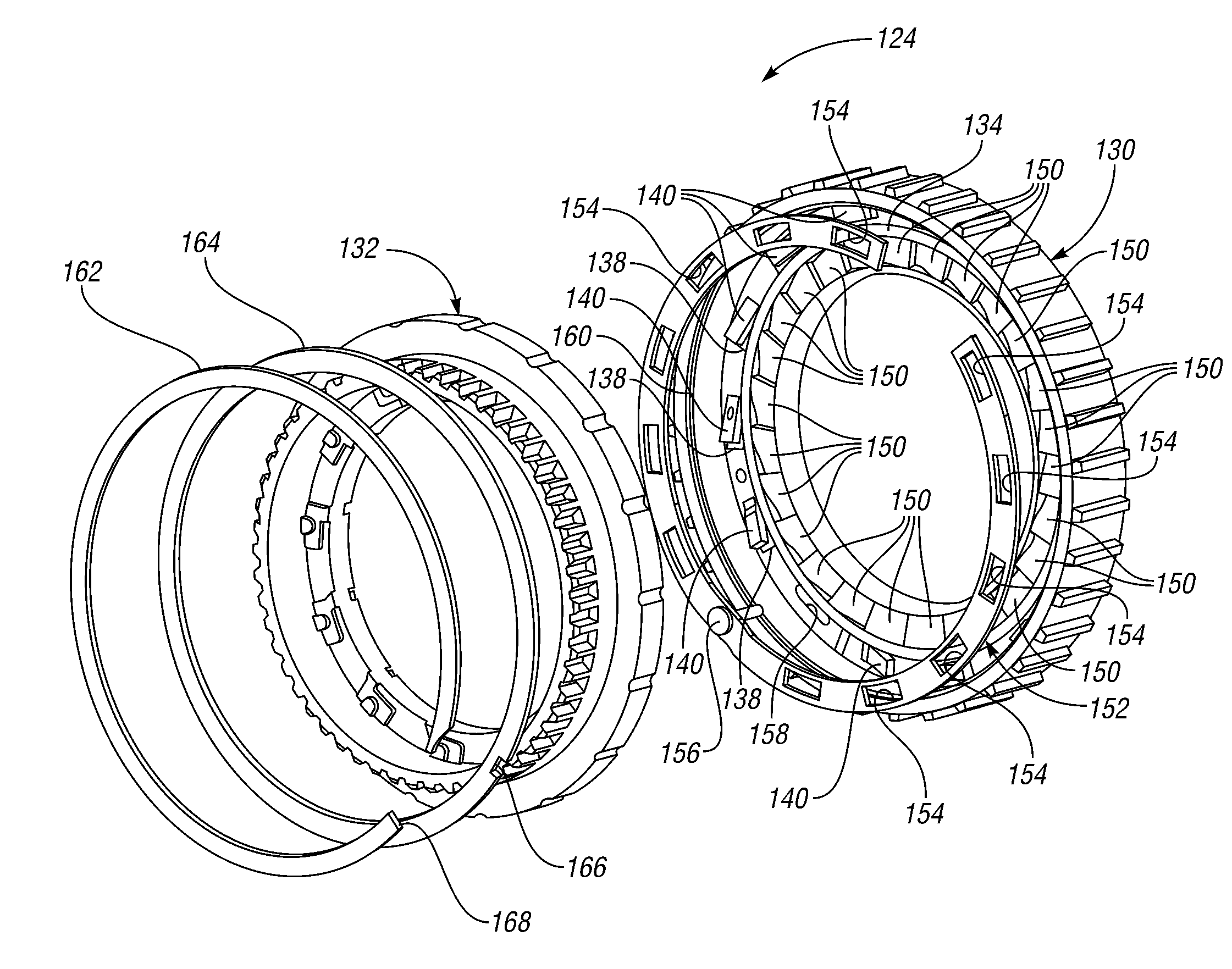
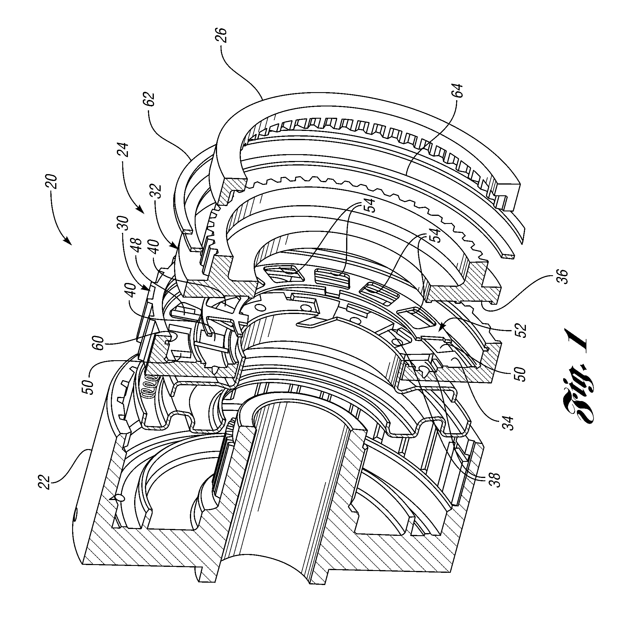
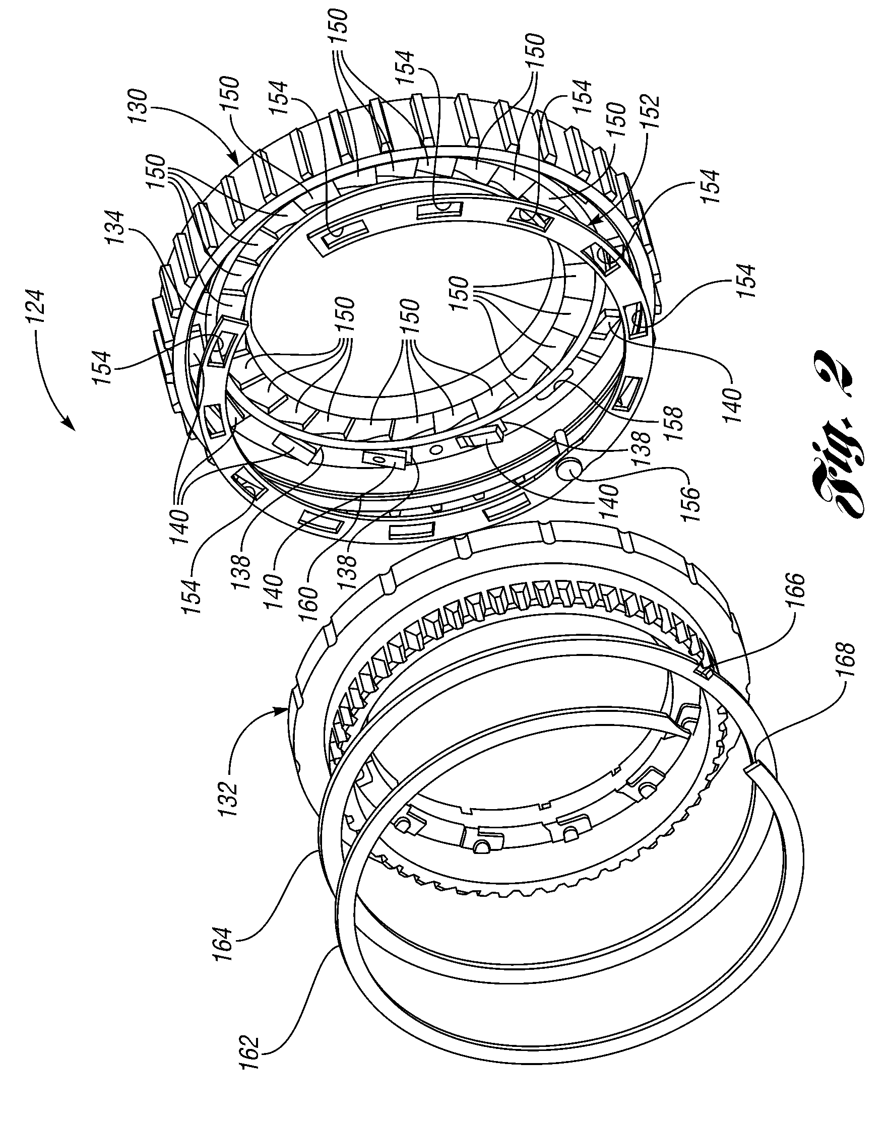
[0036]With reference to FIG. 1, a transmission, generally indicated by 20, includes a housing 22 which receives an overrunning clutch, generally indicated at 24, that is constructed in accordance with one embodiment of the present invention and utilized with a externally splined gear 26 to control torque transmission. A second embodiment of an overrunning clutch or coupling assembly is generally indicated at 124 in FIGS. 2 and 3. In general, parts of the second embodiment which are the same or similar in structure and / or function to the corresponding parts of the first embodiment have the same reference number but increased by 100.

[0037]The overrunning clutch 24 of the first embodiment includes first and second annular clutch members, generally indicated at 30 and 32 in FIG. 1. In the second embodiment, the members are generally indicated at 130 and 132 in FIGS. 2-6. The members 30 and 32 (as well as the members 130 and 132) are supported with respect to each other for relative rot...


PUM


Abstract

An overrunning coupling assembly includes a control element mounted for controlled shifting movement between coupling faces of annular coupling members relative to a first set of pockets in the first member. The control element is operable for controlling position of only reverse struts in the first set of pockets without controlling the position of forward struts in a second set of pockets in the coupling face of the second member. The control element allows at least one of the reverse struts to engage at least one of a set of locking formations on the coupling face of the second coupling member in a first position of the control element. The control element maintains the reverse struts in their pockets in a second position of the control element.

Description

CROSS-REFERENCE TO RELATED APPLICATION[0001]This application claims the benefit of U.S. provisional patent application Ser. No. 61 / 008,216 entitled “One-Way Clutch With ‘Stacked’ Struts—Each Set of Struts Having Different Radii” and filed Dec. 19, 2007.BACKGROUND OF THE INVENTION[0002]1. Field of the Invention[0003]This invention relates to overrunning coupling assemblies especially for use in vehicular automatic transmissions.[0004]2. Background Art[0005]A typical one-way clutch consists of an inner ring, an outer ring and a locking device between the two rings. The one-way clutch is designed to lock in one direction and to allow free rotation in the other direction. Two types of one-way clutches often used in vehicular, automatic transmissions include:[0006]Roller type which consists of spring loaded rollers between the inner and outer race of the one-way clutch. (Roller type is also used without springs on some applications); and[0007]Sprag type which consists of asymmetrically s...

Claims


Application Information

Patent Timeline
Patent Type & Authority Patents(United States)
IPC IPC(8): F16D63/00F16D43/00F16D11/04
CPCF16D41/125F16D41/16F16D41/14
Inventor EISENGRUBER, GREGORY M.
Owner MEANS IND INC
Learn More