Image displaying apparatus and image displaying method

a technology of image displaying apparatus and image displaying method, which is applied in the direction of instruments, cathode-ray tube indicators, data recording, etc., can solve the problems of reducing the vgs of the source voltage, difficult for the drain-source current ids to flow through the driving transistor trb>1/b>, and complicated configuration, so as to prevent horizontal-direction cords, effectively eliminate deterioration of the quality of an image being displayed

Active Publication Date: 2011-11-08
JOLED INC
View PDF18 Cites 13 Cited by
  • Summary
  • Abstract
  • Description
  • Claims
  • Application Information

AI Technical Summary

Benefits of technology

[0053]Addressing the problems described above, inventors of the present invention have innovated an image displaying apparatus capable of preventing horizontal-direction cords from being generated on the screen of the image displaying apparatus in order to effectively eliminate deteriorations of the image being displayed on the screen during simultaneous execution of a compensation preparing process and a process of compensating pixel circuits for variations of threshold voltages of driving transistors employed in the pixel circuits on a plurality of pixel-matrix rows at the same time by swapping a timing to carry out a gradation-voltage setting operation on any specific pixel-matrix row as an operation lagging behind the threshold-voltage variation compensation process, which has been carried out on all pixel-matrix rows at the same time, with a timing to carry out a gradation-voltage setting operation on a pixel-matrix row adjacent to the specific pixel-matrix row as an operation lagging behind the threshold-voltage variation compensation process in a time-axis direction (and / or a scan-line direction), and innovated an image displaying method adopted by such an image displaying apparatus.
[0056]According to the image displaying apparatus provided in accordance the above-mentioned embodiment of the present invention and the image displaying method provided in accordance with the above-mentioned embodiment of the present invention to serve as a method adopted by the image displaying apparatus, it is possible to diminish the appearance of subtle differences in emitted-light luminance between a plurality of pixel-matrix rows on which the threshold-voltage variation compensation process is carried out at the same time. As a result, it is possible to prevent horizontal-direction cords from being generated on the screen of the image displaying apparatus due to the differences in emitted-light luminance in order to effectively eliminate deteriorations of the quality of an image being displayed on the screen.
[0057]In accordance with an embodiment of the present invention, by carrying out a threshold-voltage variation compensation process of compensating a pixel circuit for variations of the threshold voltage of a driving transistor in the pixel circuit from transistor to transistor on a plurality of any specific pixel-matrix rows in the image displaying section of the image displaying apparatus at the same time, it is possible to prevent horizontal-direction cords from being generated on the screen of the image displaying apparatus in order to effectively eliminate deteriorations of the quality of an image being displayed on the screen.

Problems solved by technology

However, the configuration shown in the block diagram of FIG. 17 has a shortcoming that each pixel circuit 7 employs three NMOS transistors TR1, TR2 and TR5 which make the configuration complicated.
As the source voltage Vs rises, however, the gate-source voltage Vgs decreases, making it difficult for the drain-source current Ids to flow through the driving transistor TR1.
If the threshold-voltage variation compensation process of compensating a pixel circuit for variations of the threshold voltage Vth of the driving transistor in the pixel circuit from transistor to transistor on a plurality of consecutive pixel-matrix rows at the same time, however, it is known that there are subtle differences in light luminance between the pixel-matrix rows and, as a result, horizontal-direction cords from are generated, causing the quality of the image to deteriorate.

Method used


Image

  • Image displaying apparatus and image displaying method
  • Image displaying apparatus and image displaying method
  • Image displaying apparatus and image displaying method

Examples


first embodiment

[0081](1) Configuration of First Embodiment

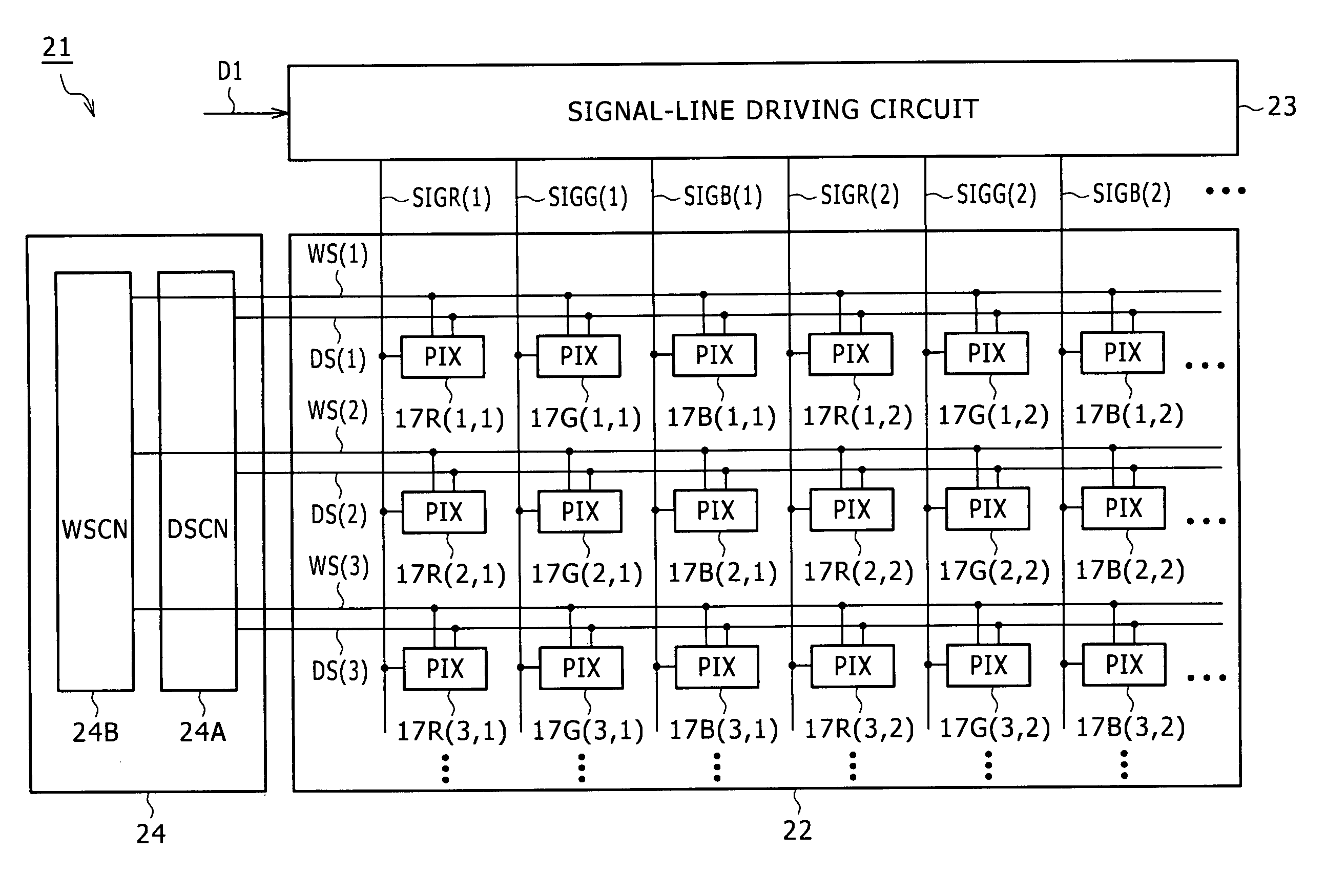
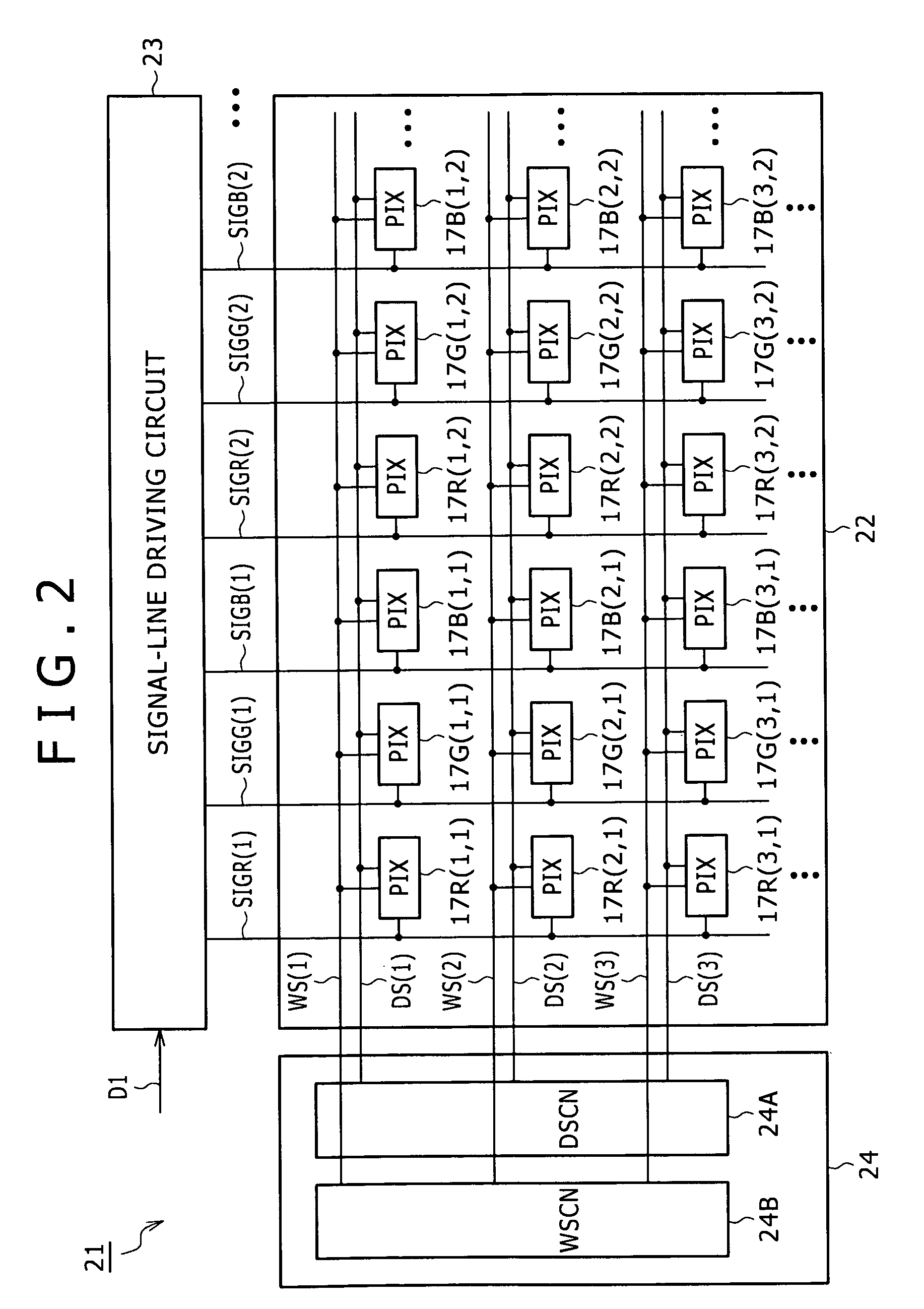
[0082]FIG. 2 is a block diagram showing an image displaying apparatus 21 according to a first embodiment of the present invention. The image displaying apparatus 21 employs an image displaying section 22 created on an insulating substrate determined in advance. In addition, the image displaying apparatus 21 is also provided with a signal-line driving circuit 23 and a scan-line driving circuit 24 which are created at locations surrounding the image displaying section 22. The image displaying section 22 is created to include a pixel matrix obtained as a result of arranging red-color pixel circuits 17R, green-color pixel circuits 17G and blue-color pixel circuits 17B. Unless specified otherwise, in the lagging behind description, the capitals R, G and B are abbreviations for the red, green and blue colors respectively. In the block diagram of FIG. 2, each of the red-color pixel circuits 17R, the green-color pixel circuits 17G and the blue-colo...

second embodiment

[0108]FIGS. 5A1 to 5F2 are timing charts of signals and states for the ith and (i+1)th pixel-matrix rows in an image displaying apparatus according to a second embodiment in the same way as the explanatory timing diagram of FIGS. 4A1 to 4F2 for the image displaying apparatus 21 according to the first embodiment. In the case of the image displaying apparatus according to the second embodiment, for any specific two adjacent pixel-matrix rows subjected to a threshold-voltage variation compensation process carried out at the same time on the two adjacent pixel-matrix rows to compensate each pixel circuit for variations of the threshold voltage Vth of the driving transistor TR1 in the pixel circuit from transistor to transistor in the image displaying apparatus 21, the timing of the falling edge of the drive scan-line driving signal DS (i) depicted by a timing chart of FIG. 5B1 as the timing chart of the ith pixel-matrix row is controlled to coincide with the timing of the falling edge o...

third embodiment

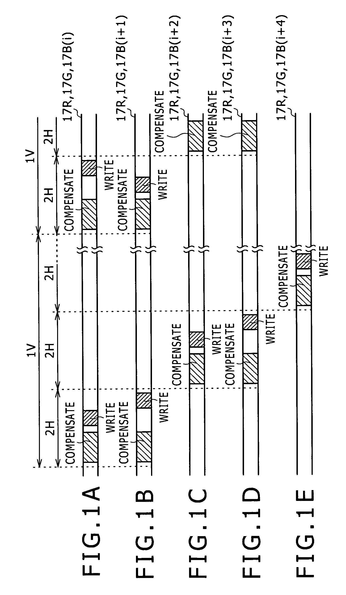
[0111]FIGS. 6A to 6E are explanatory diagrams referred to in description of operations carried out by an image displaying apparatus according to a third embodiment as the explanatory diagrams of FIGS. 1A to 1E are referred to in description of operations carried out by the image displaying apparatus 21 according to the first embodiment. In the case of the image displaying apparatus according to the third embodiment, any specific three adjacent pixel-matrix rows subjected to a threshold-voltage variation compensation process carried out at the same time on the specific three adjacent pixel-matrix rows to compensate each pixel circuit for variations of the threshold voltage Vth of the driving transistor TR1 in the pixel circuit from transistor to transistor. In addition, the timings to carry out the gradation-voltage setting operations on the three adjacent pixel-matrix rows are interchanged with each other with each other sequentially by rotating the timings over the three adjacent p...


PUM

PropertyMeasurementUnit
threshold voltageaaaaaaaaaa
luminanceaaaaaaaaaa
threshold-voltageaaaaaaaaaa

Abstract

An image displaying apparatus is configured to display a desired image on an image displaying section employed in the image displaying apparatus by making use of a signal-line driving circuit and a scan-line driving circuit to drive pixel circuits. Each of the pixel circuits employs at least a light emitting device, a signal-level holding capacitor, a driving transistor for driving the light emitting device and a signal writing transistor. The signal-line driving circuit and the scan-line driving circuit drive each of the pixel circuits so as to put the light emitting device employed in the pixel circuit in a no-light emission state of emitting no light in a no-light emission period and a light emission state of emitting light in a light emission period repeatedly.

Description

BACKGROUND OF THE INVENTION[0001]1. Field of the Invention[0002]In general, the present invention relates to an image displaying apparatus as well as an image displaying method adopted by the image displaying apparatus, and can be applied typically to an image displaying apparatus adopting an active matrix driving technique provided for organic EL (Electro Luminescence) devices employed in the image displaying apparatus. In particular, the present invention relates to an image displaying apparatus capable of preventing horizontal-direction cords from being generated on the screen of the image displaying apparatus in order to effectively eliminate deteriorations of the quality of an image being displayed on the screen during simultaneous execution of a process of compensating pixel circuits for variations of threshold voltage of driving transistors employed in the pixel circuits on a plurality of pixel-matrix rows at the same time by swapping a timing to carry out a gradation-voltage...

Claims


Application Information

Patent Timeline
Patent Type & Authority Patents(United States)
IPC IPC(8): G11B7/00
CPCG09G3/3233G09G2300/043G09G2310/0208G09G2310/0251G09G2310/0262G09G2320/0233G09G2320/0247G09G3/20G09G3/30
Inventor ASANO, MITSURUYAMAMOTO, TETSUROUCHINO, KATSUHIDE
Owner JOLED INC
Why Eureka
Try Eureka