Image forming apparatus, developing unit thereof and method for controlling developing unit

a technology of developing unit and developing unit, which is applied in the direction of electrographic process apparatus, printing, instruments, etc., can solve the problems of auger or housing breakage, and achieve the effect of preventing the breakage of components and smooth solving the concentration of developers

Inactive Publication Date: 2011-11-08
S PRINTING SOLUTION CO LTD
View PDF1 Cites 4 Cited by
  • Summary
  • Abstract
  • Description
  • Claims
  • Application Information

AI Technical Summary

Benefits of technology

[0012]The present general inventive concept provides an image forming apparatus that is capable of smoothly solving the concentration of a developer and preventing the breakage of components when the developer circulating in an agitating space and a supply space in a developing unit by augers mounted in the spaces is concentrated on gates which connect the agitating space and the supply space.

Problems solved by technology

However, in the above conventional developing unit of the image forming apparatus, the developer may be concentrated on one of the gates due to the tilting during conveyance or installation, or the irregular operation of the augers.
In this case, because the developer cannot be transferred smoothly through the gates, a transfer pressure of the developer at the gate increases and a torque of the rotating auger increases excessively, which may cause breakage of the components like the auger or the housing.

Method used


Image

  • Image forming apparatus, developing unit thereof and method for controlling developing unit
  • Image forming apparatus, developing unit thereof and method for controlling developing unit
  • Image forming apparatus, developing unit thereof and method for controlling developing unit

Examples


Embodiment Construction

[0046]Reference will now be made in detail to exemplary embodiments of the present general inventive concept, examples of which are illustrated in the accompanying drawings, wherein like reference numerals refer to like elements throughout. The embodiments are described below to explain the present general inventive concept by referring to the figures.

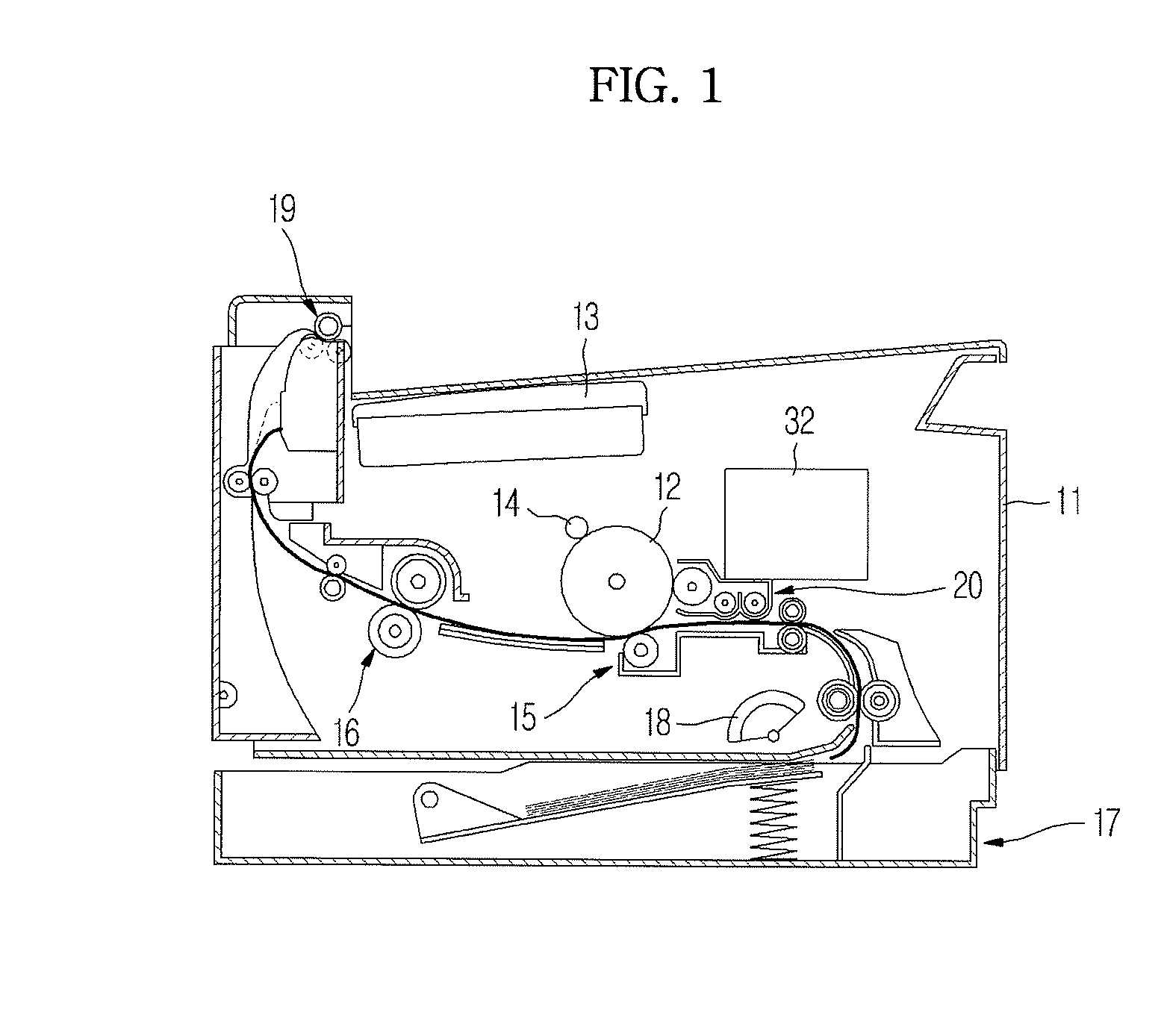
[0047]As illustrated in FIG. 1, an image forming apparatus according to an exemplary embodiment of the present general inventive concept includes a main body 11 which forms an external appearance, a photosensitive body 12 on which an electrostatic latent image is formed, a light scanning unit 13 which scans a beam onto the photosensitive body 12, a charge unit 14 which charges the photosensitive body 12 with a predetermined electric potential, a developing unit 20 which supplies (attaches or transfers) a toner to the photosensitive body 12 to develop the electrostatic latent image into a visible image, a transfer unit 15 which transfer...


PUM


Abstract

An image forming apparatus, a developing unit thereof and a method of controlling the developing unit. The image forming apparatus includes a photosensitive body on which an electrostatic latent image is formed, a light scanning unit which scans a beam onto the photosensitive body, a developing unit which includes a housing having an agitating space and a supply space, the agitating space and the supply space communicating with each other through two gates to circulate a developer, an agitating auger rotatably mounted in the agitating space to transfer the developer, a supply auger rotatably mounted in the supply space to transfer the developer, and a magnetic roller which receives the developer by the supply auger and adheres the developer to the photosensitive body, a rotation control unit which controls rotation of the agitating auger and the supply auger, and a transfer unit which transfers a visible image formed on the photosensitive body onto a printing medium. When the developer is concentrated on any one of two gates, one of the augers, which is positioned on a downstream side of the gate on which the developer is concentrated, temporarily stops rotating by the rotation control unit, and the developer concentrated on the gate is transferred from the gate by the other one of the augers, which is positioned on an upstream side of the gate on which the developer is concentrated.

Description

CROSS-REFERENCE TO RELATED APPLICATIONS[0001]This application claims the benefit of Korean Patent Application No. 2007-0014907, filed on Feb. 13, 2007 in the Korean Intellectual Property Office, the disclosure of which is incorporated herein in its entirety by reference.BACKGROUND OF THE INVENTION[0002]1. Field of the Invention[0003]The present general inventive concept relates to an image forming apparatus, and more particularly, to an image forming apparatus that uses a developer, a developing unit thereof and a method of controlling the developing unit.[0004]2. Description of the Related Art[0005]An image forming apparatus is an apparatus that prints a black and white image or a color image on a printing medium, e.g., paper, according to an inputted image signal, for example, a laser printer, an ink-jet printer, a copying machine, a multi-function printer, a fax machine, etc. An image forming apparatus is classified as an electrophotographic type in which a beam is scanned onto a...

Claims


Application Information

Patent Timeline
Patent Type & Authority Patents(United States)
IPC IPC(8): G03G15/08
CPCG03G15/0877G03G15/0893G03G2215/0822G03G2215/0838G03G15/08
Inventor KIM, DAE-HO
Owner S PRINTING SOLUTION CO LTD
Why Eureka
Try Eureka