
a cooling device

A technology of equipment and sprinkler, which is applied in the field of cooling equipment, can solve the problems of easy ash in the nozzle hole, poor mixing effect of cold water and normal temperature water, and heatstroke of workers, so as to improve the uniformity of mixing, improve the efficiency of sprinkling water, and improve work efficiency. Effect

Active Publication Date: 2019-09-13
浙江章华保健美发实业有限公司
View PDF5 Cites 0 Cited by
  • Summary
  • Abstract
  • Description
  • Claims
  • Application Information

AI Technical Summary

Problems solved by technology

[0002] Summer is coming, the weather is hot, factories, workshops and other places emit a lot of heat due to long-term mechanical operation, resulting in high indoor temperature, which is extremely unfavorable to the health of workshop workers, and can easily lead to heat stroke
These places generally do not install air conditioners, but use simple fans and sprinkle water on the ground and the air to achieve the purpose of cooling. The existing sprinkler cooling measures rely on manual watering or using pipes to pour water, which is time-consuming and laborious. Some special sprinkler devices Ice water or ice cubes can be added to the water to achieve the cooling function efficiently, but the mixing effect of the internal cold water and normal temperature water is poor, and the nozzle holes of the pouring head are exposed for a long time, so the nozzle holes on the spray pipe are easy to enter The ash causes the nozzle holes to be blocked, thereby delaying the normal sprinkling and cooling work

Method used


Image

  • a cooling device
  • a cooling device
  • a cooling device

Examples


Embodiment Construction

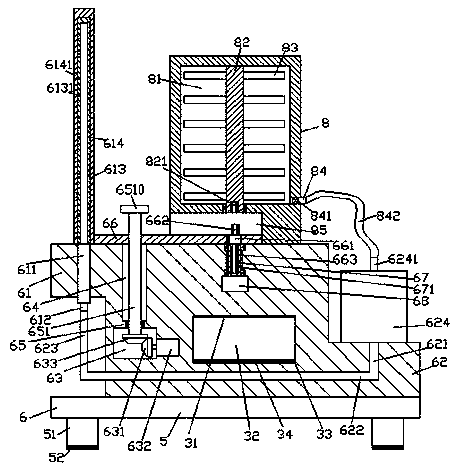
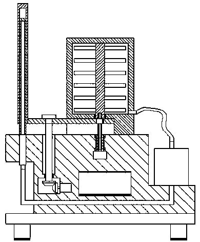
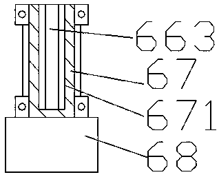
[0020] like Figure 1-Figure 3 As shown, a cooling device of the present invention includes a base 5 and a sprinkling device 6 arranged on the top of the base 5 , the top of the left side of the sprinkling device 6 is provided with a first flange block 61 , and the sprinkling device 6 The bottom of the right side of the device 6 is provided with a second flange block 62, and the first flange block 61 is fixed with a first delivery tube 611 extending up and down, and the top of the first flange block 61 is provided with a bottom and a The top of the first delivery pipe 611 is extended with a sprinkling channel 613 fixedly connected to the tip. The outer surface of the sprinkling channel 613 is smoothly provided with a set 614. The left side of the sprinkling channel 613 is provided with a sprinkling hole 6131. ​​The set 614 On the left side, there is a sprinkling part 6141 intermixed with the sprinkling hole 6131 on the sprinkling channel 613. The sprinkling device 6 is provide...


PUM


Abstract

The invention discloses novel cooling equipment. The novel cooling equipment comprises a base platform and a watering device arranged on the top of the base platform; a first convex edge block is arranged on the top of the left side face of the watering device, and a second convex edge block is arranged at the bottom of the right side face of the watering device; a first conducting pipe extendingup and down is fixedly arranged in the first convex edge block; a watering channel with the bottom fixedly connected with the top extending end of the first conducting pipe is formed in the top of thefirst convex edge block; a sleeve part is smoothly arranged on the outer surface of the watering channel; a containing box is arranged on the top of the watering device and internally provided with acontaining cavity; a slide-guiding groove which extends towards the left side is formed in the position, below the bottom of the containing cavity, in the containing box; and a mixing shaft which extends up and down is arranged in the containing cavity, and the top extending end of the mixing shaft is connected with the top wall in the containing cavity in a rotating fit mode. The novel cooling equipment is simple in structure and convenient to operate, opening and closing work of the watering channel and the sleeve part can be automatically controlled, the service life is prolonged, mixing work can be completed through automatic matching connection, and the cooling effect is improved.

Description

technical field [0001] The invention relates to the field of indoor cooling, in particular to cooling equipment. Background technique [0002] Summer is coming, the weather is hot, factories, workshops and other places emit a lot of heat due to long-term mechanical operation, resulting in high indoor temperature, which is extremely unfavorable to the health of workshop workers, and can easily lead to heat stroke. These places generally do not install air conditioners, but use simple fans and sprinkle water on the ground and the air to achieve the purpose of cooling. The existing sprinkler cooling measures rely on manual watering or using pipes to pour water, which is time-consuming and laborious. Some special sprinkler devices Ice water or ice cubes can be added to the water to achieve the cooling function efficiently, but the mixing effect of the internal cold water and normal temperature water is poor, and the nozzle holes of the pouring head are exposed for a long time, s...

Claims


Application Information

Patent Timeline
Patent Type & Authority Patents(China)
IPC IPC(8): F24F5/00F24F11/89
Inventor 张曙光
Owner 浙江章华保健美发实业有限公司
Learn More