Concrete and light gauge cold formed steel building structure with beam and floor extending over a load bearing stud wall and method of forming

Active Publication Date: 2011-11-15
THE STEEL NETWORK
View PDF36 Cites 30 Cited by
  • Summary
  • Abstract
  • Description
  • Claims
  • Application Information

AI Technical Summary

Problems solved by technology

Because of that, overall

Method used


Image

  • Concrete and light gauge cold formed steel building structure with beam and floor extending over a load bearing stud wall and method of forming
  • Concrete and light gauge cold formed steel building structure with beam and floor extending over a load bearing stud wall and method of forming
  • Concrete and light gauge cold formed steel building structure with beam and floor extending over a load bearing stud wall and method of forming

Examples


Embodiment Construction

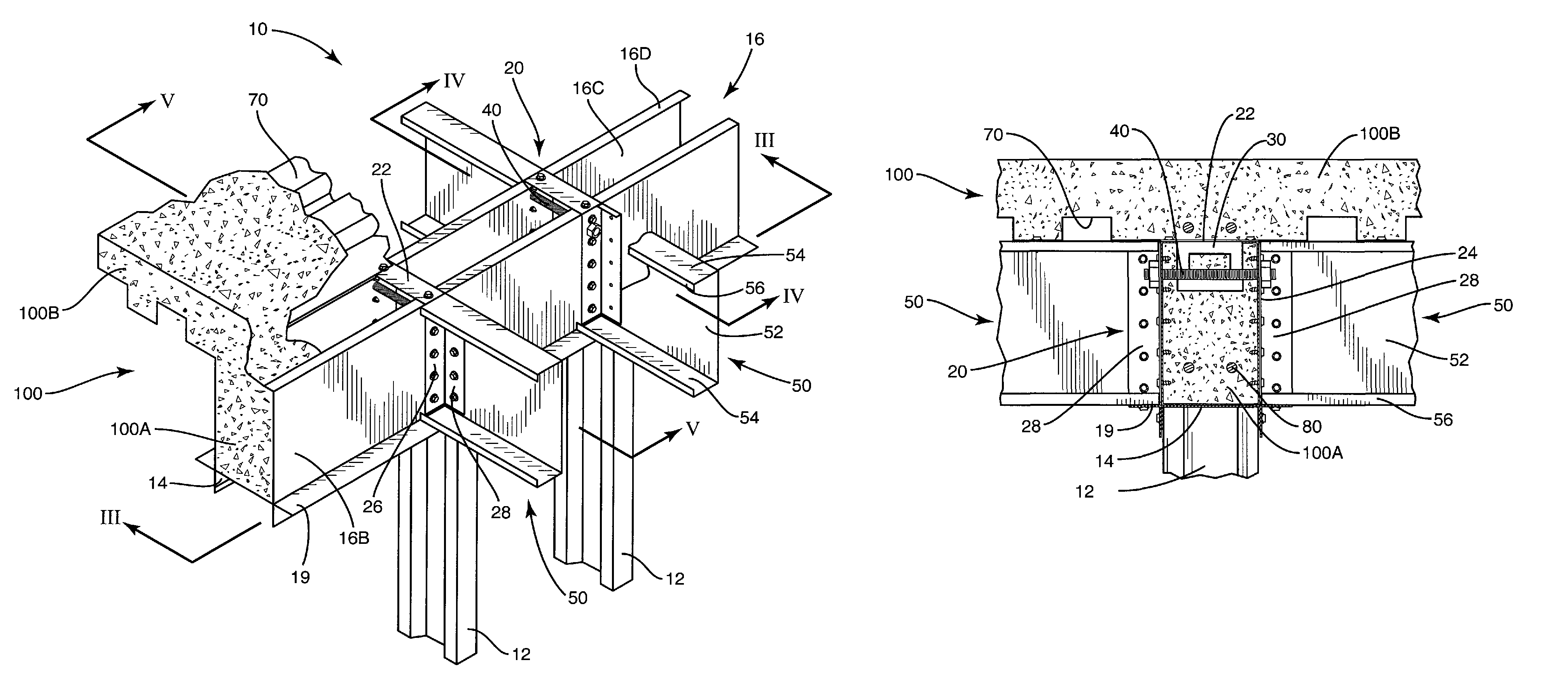
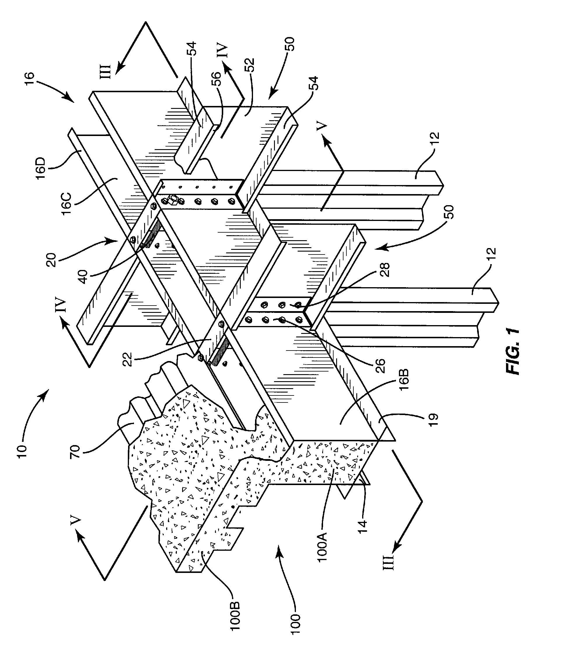
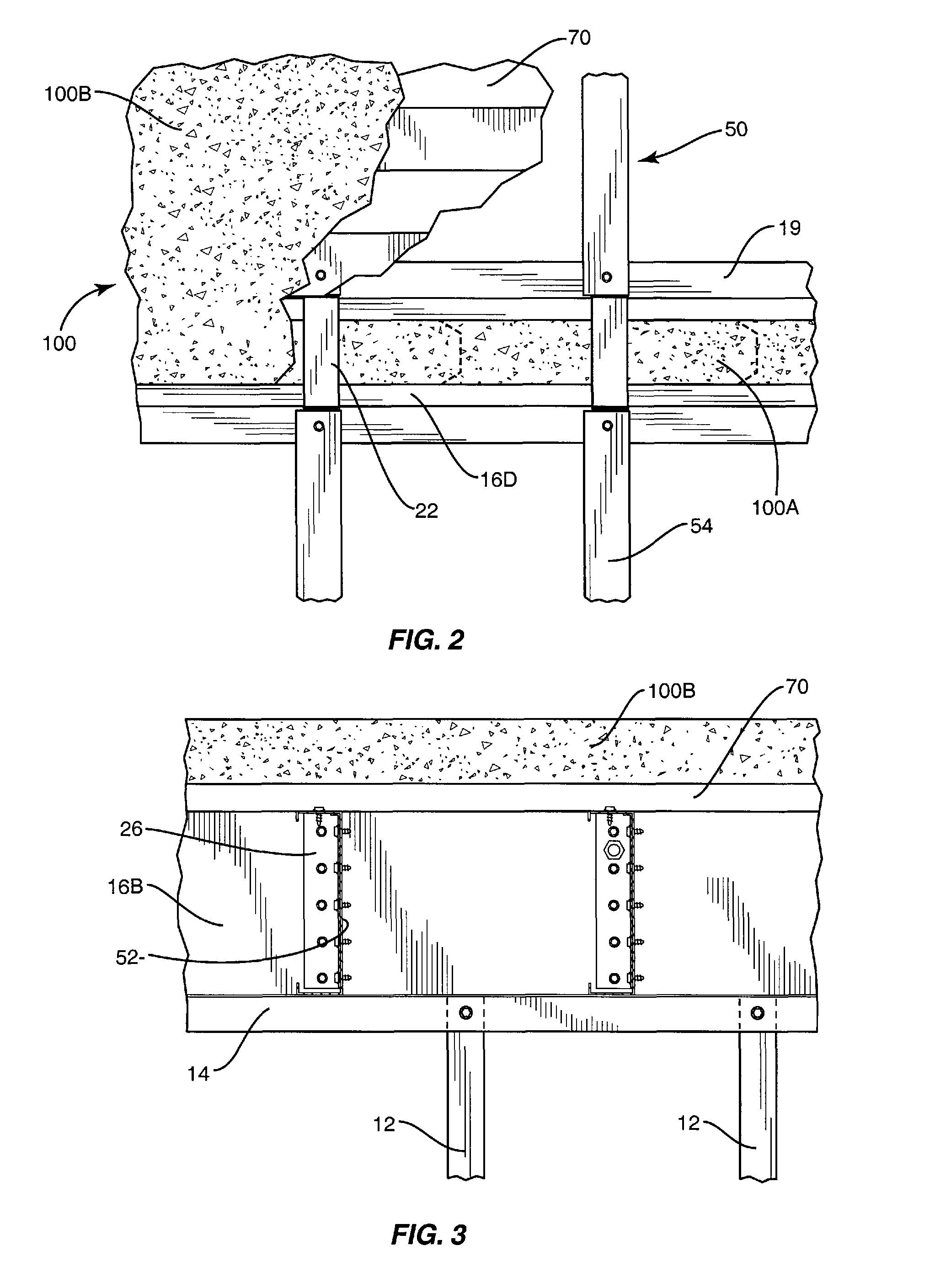
[0017]With further reference to the drawings, a building structure is shown therein and indicated generally by the numeral 10. Building structure 10 entails a building system for uniformly distributing floor loads utilizing cold formed steel floor joists in load-bearing stud wall applications. As will be appreciated from subsequent discussions, the building structure 10 combines reinforced concrete and light gauge cold formed steel. With respect to the concrete component of the building structure 10, a monolithic concrete structure is formed including a floor portion and a beam or header portion. The beam or header portion is formed by a light gauge cold formed steel component that is structural and also functions to form the beam or header portion of the monolithic concrete structure.

[0018]Turning to the drawings, and particularly to FIG. 1, the building structure 10 includes a series of spaced-apart studs 12. The studs 12 are light gauge cold formed steel studs. Studs 12 typically...


PUM


Abstract

A series of spaced-apart light gauge cold formed steel studs underlie an elongated light gauge cold formed steel channel or box. A series of joist supports are connected to the channel and a series of joists, formed of a light gauge cold formed steel, are connected to the joist supports and extend outwardly from the box. Decking is supported on the joist. Concrete is poured into the channel to form a reinforced header or beam, and concrete is also poured onto the decking to form a concrete floor. Together, the concrete floor and header form a monolithic concrete structure that enables the joist to be misaligned with studs.

Description

FIELD OF THE INVENTION[0001]The present invention relates to building structures and, more particularly, to a combination concrete and light gauge cold formed steel building structure.BACKGROUND OF THE INVENTION[0002]Typically in light gauge steel construction, load bearing components, such as studs and joists, are aligned. That is, load bearing studs on an upper floor are generally aligned with load bearing studs on a lower floor. Likewise, joists are usually aligned with studs in order to carry loads. This, of course, mandates a fairly rigid design with respect to studs and joists used in load bearing structures. Because of that, overall designs are less flexible.SUMMARY[0003]A load-bearing wall is provided that includes a series of spaced-apart studs that support a beam former and a concrete beam or header that extends through the beam former. The beam former forms a part of the building structure even after a concrete beam or header is formed therein.[0004]Another aspect of the ...

Claims


Application Information

Patent Timeline
IPC IPC(8): E04B1/16E04B1/24E04B5/19E04G21/02
CPCE04B5/19E04B5/40E04B1/24E04B2001/2484E04B2001/2448E04B2001/2478E04B2001/2415
Inventor DIGIROLAMO, EDWARD R.ABDEL-RAHMAN, NABILTRESTAIN, THOMASBOOTH, MICHAELBENNETT, GARYPEKOZ, TEOMAN
Owner THE STEEL NETWORK
Why Eureka
Try Eureka